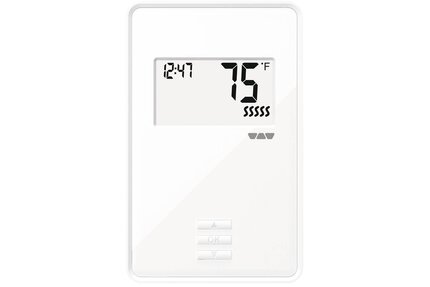
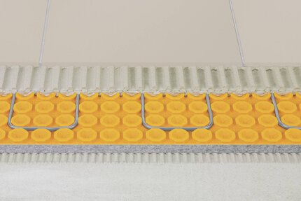
Schluter®-DITRA-HEAT-E-RR
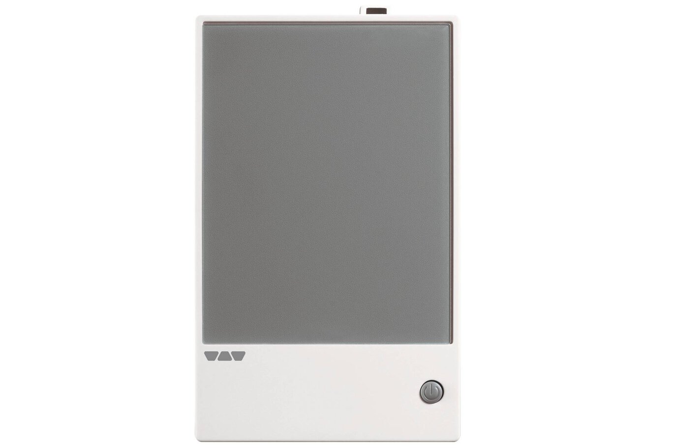
Módulo de alimentación que amplia la potencia de salida del sistema DITRA-HEAT

- Amplia la potencia de salida en 15 Amps en aplicaciones de gran superficie
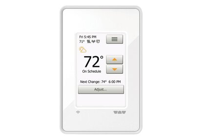
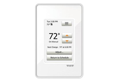
- Controlado por los termostatos DITRA-HEAT-E-RT o DITRA-HEAT-E-R a través de un cable de señal de baja tensión de 2 conductores 20 AWG
- Resiste cables de 120 y 240 V
- Construidos en GFCI Clase A
Find recommended accessories here

Estimador DITRA-HEAT
Calcule sin esfuerzo sus necesidades de membranas y cables.
The power module may be used in conjunction with the DITRA-HEAT-E-WIFI, DITRA-HEAT-E-RT, or DITRA-HEAT-E-R thermostats when the heating load exceeds 15 amps (e.g., in large floor applications) to maintain a single point of control. Up to 16 DITRA-HEAT-E-RR power modules may be connected in series via low voltage signal wire to a single DITRA-HEAT-E-WIFI, DITRA-HEAT-E-RT, or DITRA-HEAT-E-R thermostat.
Please refer to the Quick guide and Schluter®-DITRA-HEAT Installation Handbook for complete DITRA-HEAT system installation instructions.
1. The power supply must be shut off and all electrical connections must be made by a qualified person, according to the electrical and building codes effective in your region.
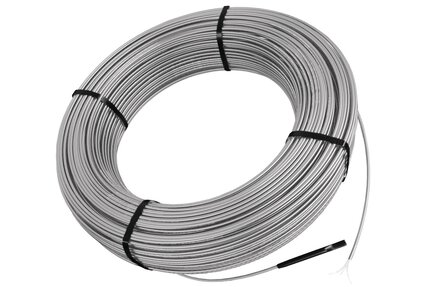
2. Connect the heating cable ground braid to the ground wire from the electrical panel.
3. Remove the faceplate from the module power base by loosening the screw and tilting the module upward. Remove the back cover clip as well.
4. For ease of installation, form the electrical line wires into an “M” or accordion shape. This will make it easier to fold them neatly into the electrical box. Loosen the load screws at the top of the module until they stop.
5. Insert the heating cable conductors into the load terminals from the bottom. Since there is no polarity, either heating cable conductor can be connected to either load terminal.
6. Secure the conductors by tightening the screws.
7. Insert the electrical line wires into the line terminals from the top. Refer to the back of module for proper wiring configuration.
8. Secure the wires by tightening the screws and fold the wires into the electrical box. Align and secure the module power base to the electrical box.
9. To install signal wire, connect a 2 conductor 20 AWG wire from terminal A on the thermostat to terminal C on the power module and from terminal B on thermostat to terminal D on power module. Note: Wiring orientation is required for power module to operate correctly.
10. Secure the conductors by tightening the screws.
11. The power, heating cable, and signal connections are now complete. Replace the power module faceplate and tighten the screw at the bottom of the unit.
Note: Up to 16 DITRA-HEAT-E-RR power modules may be connected in series to a single DITRA-HEAT-E-WIFI, DITRA-HEAT-E-RT, or DITRA-HEAT-E-R thermostat.
FAQ
How do I connect an expansion unit/power module to the DITRA-HEAT-E-WIFI, DITRA-HEAT-E-RT or DITRA-HEAT-E-R thermostats?
Connect a 2 conductor 20 AWG wire from terminal A on the thermostat to terminal C on the power module and from...
Read morec-UL-us according to the following standards:
UL E-file: E157297
GFCI: UL 943
CSA C22.2, No. 144. 1-06

Watch & Learn
About the product

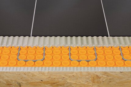
Schluter®-DITRA-HEAT: System Components
Mike Holmes on Schluter®-DITRA-HEAT
Find some existing tutorials and project documentation videos to learn how-to get the best out of our products - for more fun in your life, start now!
Watch more videos / playlists