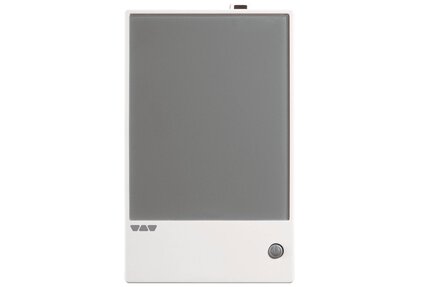
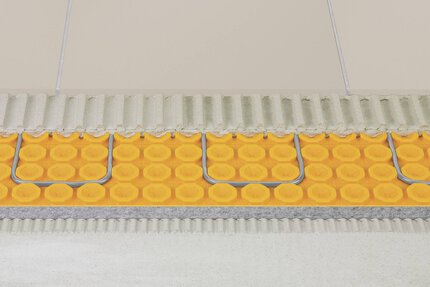
Schluter®-DITRA-HEAT-E-R
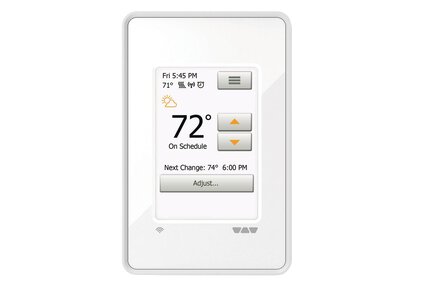
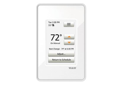
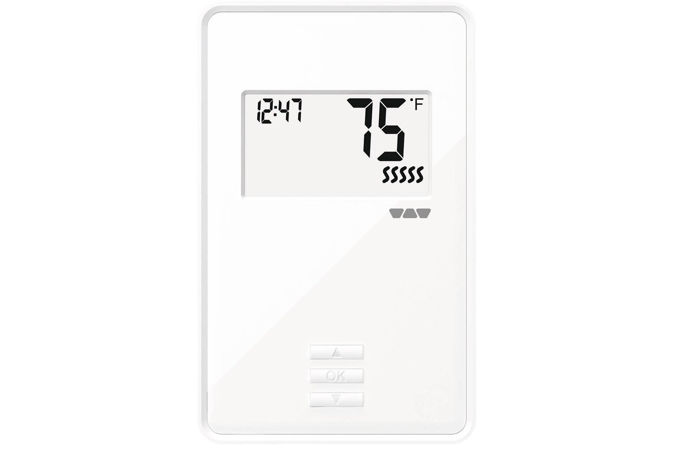
Non-programmable digital thermostat for the DITRA-HEAT system

- Indicador digital con pantalla retroiluminada
- Simple operación encendido/apagado (on/off)
- Soporta cables de 120 v y 240 V
- GFCI integrado de 5 mA
- Disponible en blanco brillante
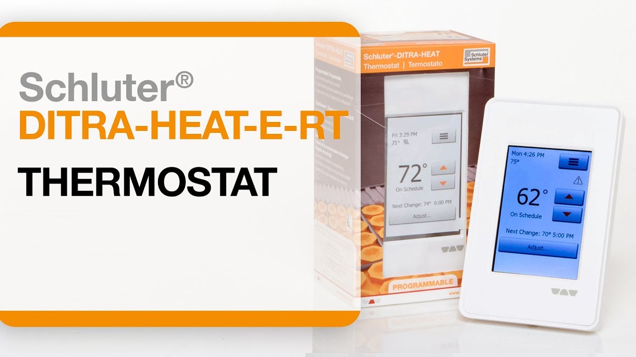

Find recommended accessories here

Estimador DITRA-HEAT
Calcule sin esfuerzo sus necesidades de membranas y cables.
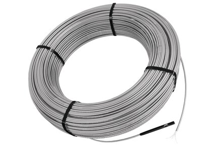
DITRA-HEAT-E-R is a non-programmable digital thermostat used to control the DITRA-HEAT-E-HK heating cables (either 120 V or 240 V).The thermostat features a built in Class A ground fault circuit interrupter (GFCI) with indicator light and includes a floor temperature sensor. DITRA-HEAT-E-R is operated via a simple on/off switch. Two heating cables may be connected to the thermostat, up to the total heating load limit of 15 amps. The DITRA-HEAT-E-RR power module may be used in conjunction with the thermostat when the heating load exceeds 15 amps (e.g., in large floor applications) to maintain a single point of control.
Please refer to the Quick Guide and Schluter®-DITRA-HEAT Installation Handbook for complete DITRA-HEAT system installation instructions.
1. DITRA-HEAT-E-R must be installed in an electrical box. A single gang, deep electrical box or a double gang electrical box with a single gang mud ring is recommended to provide room for the wiring.
2. The power supply must be shut off and all electrical connections must be made by a qualified person, according to the electrical and building codes effective in your region.
3. Connect the heating cable ground braid to the ground wire from the electrical panel.
4. Remove the faceplate from the thermostat power base by loosening the screw and tilting the thermostat upward. Remove the back cover clip as well.
5. For ease of installation, form the electrical line wires into an “M” or accordion shape. This will make it easier to fold them neatly into the electrical box. Loosen the load screws at the top of the thermostat until they stop.
6. Insert the heating cable conductors into the load terminals from the bottom. Since there is no polarity, either heating cable conductor can be connected to either load terminal.
7. Secure the conductors by tightening the screws.
8. Insert the electrical line wires into the line terminals from the top. Refer to the back of thermostat for proper wiring configuration.
9. Secure the wires by tightening the screws and fold the wires into the electrical box.
10. Align and secure the thermostat power base to the electrical box.
11. Pase los sensores de temperatura del piso a través de la abertura situada en la parte inferior derecha de la base de alimentación del termostato. Pegue con cinta adhesiva el sensor secundario de temperatura del piso y fíjelo a la base de alimentación.
12. Pele los extremos del sensor de temperatura del piso para exponer los cables y facilitar la instalación. Inserte los cables del sensor de temperatura del piso en los terminales C y D. Tenga en cuenta que los cables del sensor de temperatura del piso no tienen polaridad y pueden intercambiarse entre los terminales C y D. Apriete los tornillos para fijar los cables.
13. Las conexiones de alimentación, cable calefactor y sensor de temperatura del piso ya están completas. Vuelva a colocar la placa frontal del termostato y apriete el tornillo de la parte inferior de la unidad.
Nota: se pueden conectar dos cables calefactores DITRA-HEAT-E-HK y ser controlados por un solo termostato DITRA-HEAT-E-R si la corriente total es inferior a 15 amperios. Los cables calefactores deben conectarse en paralelo de acuerdo con los códigos eléctricos y de construcción aplicables. No se pueden conectar varios cables calefactores DITRA-HEAT-E-HK de más de 15 amperios a un solo termostato DITRA-HEAT-E-R. Deben utilizarse termostatos DITRA-HEAT-E-R adicionales o el termostato DITRA-HEAT-E-R puede combinarse con los módulos de potencia DITRA-HEAT-E-RR.
FAQ
¿Cómo conecto los cables calefactores Schluter®-DITRA-HEAT-E-HK a un termostato Schluter®-DITRA-HEAT-E-RSD?
Para obtener instrucciones sobre la conexión del termostato DITRA-HEAT-E-RSD, consulte las Guías del usuario del termostato Schluter®-DITRA-HEAT o...
Read more¿Cómo programo el termostato Schluter®-DITRA-HEAT-E-RSD?
Consulte la guía del usuario del termostato DITRA-HEAT DHE RS D/BW para obtener instrucciones escritas o vea el vídeo Consejos, trucos y preguntas frecuentes...
Read more¿Se puede conectar más de un cable calefactor DITRA-HEAT-E-HK a los termostatos Schluter®-DITRA-HEAT-E?
Se pueden conectar varios cables calefactores DITRA-HEAT-E-HK y controlarlos con un solo termostato DITRA-HEAT-E si la corriente total es inferior a 15 amperios…
Read more¿Qué tamaño de caja eléctrica se recomienda para un termostato Schluter-DITRA-HEAT-E?
Recomendamos una caja eléctrica profunda de un solo elemento o una caja eléctrica de doble elemento con un marco empotrable simple para proporcionar suficiente…
Read more¿Cómo conecto una unidad de expansión/módulo de potencia a los termostatos DITRA-HEAT-E-WIFI, DITRA-HEAT-E-RT o DITRA-HEAT-E-R?
Conecte un cable 20 AWG de 2 conductores desde el terminal A del termostato al terminal C del módulo de potencia y...
Read more
DITRA-HEAT-R es c-UL-us según las siguientes normas:
Thermostat: UL 60730
CSA- E60730
UL E-file: E157297
GFCI: UL 943
CSA C22.2, No. 144. 1-06

Watch & Learn
About the product

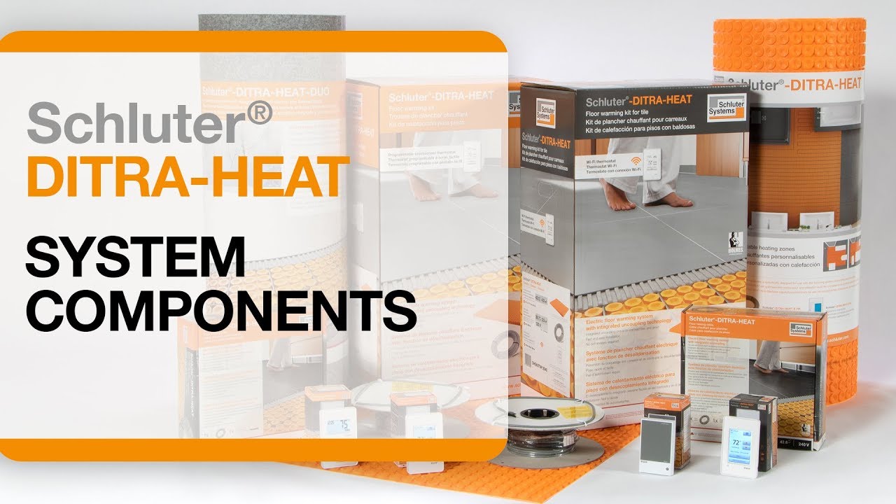
Schluter®-DITRA-HEAT Instalación: Componentes del sistema
Schluter®-DITRA-HEAT-E-RT Termostato Instalación

Schluter®-DITRA-HEAT Instalación: Planificar para instalar
Find some existing tutorials and project documentation videos to learn how-to get the best out of our products - for more fun in your life, start now!
Watch more videos / playlists