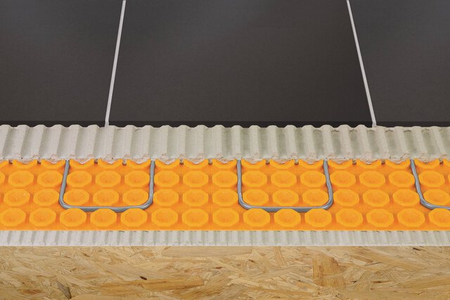
Installation instructions for Schluter®-KERDI-SHOWER-FRS

Refer to the Schluter®-KERDI-SHOWER-FRS Installation Handbook for complete installation instructions and specifications for shower applications.


PLANNING

1. Verify that joist spacing does not exceed 19.2" (49 cm) o.c.
2. 5/8" (1.6 cm) subfloor applications require the use of Schluter®-KERDI-SHOWER-FRS Shims (Item No.: KS FRS SH60)
3. *Pre-drilling for 1-5/8" and 2-3/4" wood-to-metal screws can increase speed and ease of installation. Use a 1/8" (3.2 mm) drill bit with #10 screws.
4. Obtain the required 3/4" (2 cm) plywood for FRS Inserts. Plywood must meet local building code requirements for subflooring.
5. Obtain materials for filler pieces. OSB or Plywood can be used.
6. Confirm floor cavity depth will accommodate all plumbing components after the 11/16" recess.
7. Use only the fasteners provided for brackets and inserts.
8. The tray edge and membrane must be flush. Use the COMPONENT THICKNESS TABLE to plan accordingly. FRS is recommended for use with Schluter®-KERDI-SHOWER-TT trays due to their thin perimeter.
9. See FRS KIT AND BRACKET KIT SELECTION GUIDE below for guidance on selecting kits based on the size and conditions of your installation.
Additional brackets may be required if substantial blocking is present in the floor

Special considerations for curbless showers

Check local code(s) to determine if secondary drainage is required. Schluter® -KERDI-DRAIN-F may be used.
Consider shower spray direction and curtain/barrier placement. Spray directed to the base of a curtain/barrier can be driven out of the shower area; plan fixture locations accordingly.
Curbless tiled showers rely on the floor slope to effectively contain water in the immediate shower area and direct it to the drain.
Proactive management of drain clogs is particularly important in curbless shower installations; ensure the end user is informed accordingly.
Various building codes and other sources, such as the Americans with Disabilities Act (ADA), include specific requirements for disabled access and must be consulted when applicable.

INSTALLATION

1

Create access at the bottom of the wall for P-bracket attachment by removing enough wallboard to fit your drill, screws, and hands.

2

Trace the tray on the floor, allowing for wallboard thickness and adding 1/8" (3.2 mm) of extra space on all sides for bracket thickness and cutting imperfections.


3

Cut out the traced section.

Set the appropriate cutting depth and use caution to avoid damaging joists.
Use a flush-cut or oscillating tool to cut as flush as possible along the bottom plate of the wall.
4

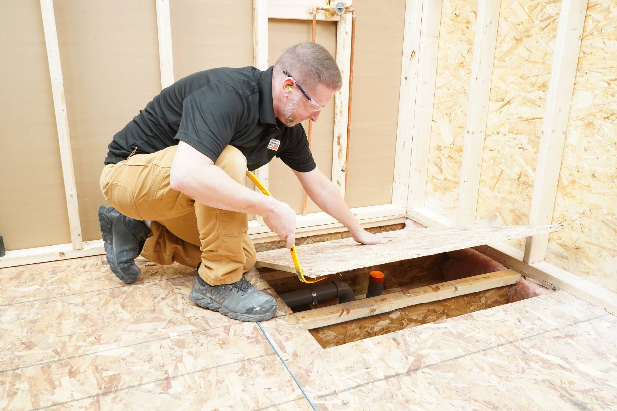
Remove all accessible subfloor fasteners, then pry up the cut-out sections using appropriate tools. Use caution not to damage joists or remaining subfloor as some glue and fasteners may remain.

Caution: Do not step between joists.
5

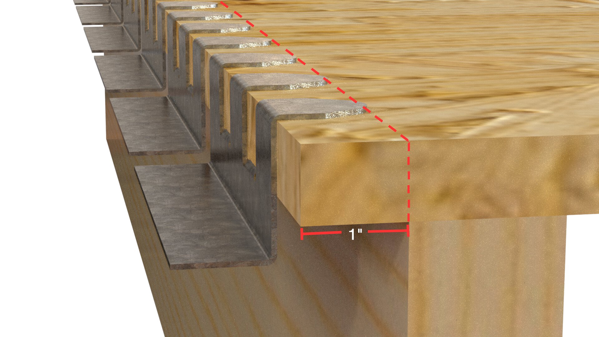
Trace out and extend the cutout section up to the next joist while leaving 1" (2.5 cm) of overhanging subfloor intact for P-bracket attachment.
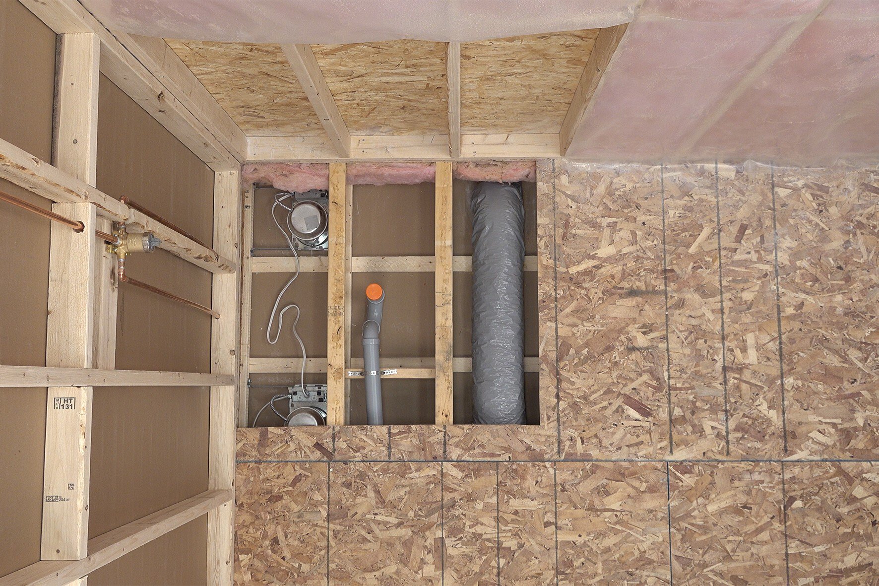
If the cut edge already lands closer than 1" (2.5 cm), the cutout must be extended to the adjacent bay.
6

Clean up the edges of the opening and the tops of joists by removing any remaining glue or splinters, etc.


7

Verify the opening dimensions are correct before proceeding.
8

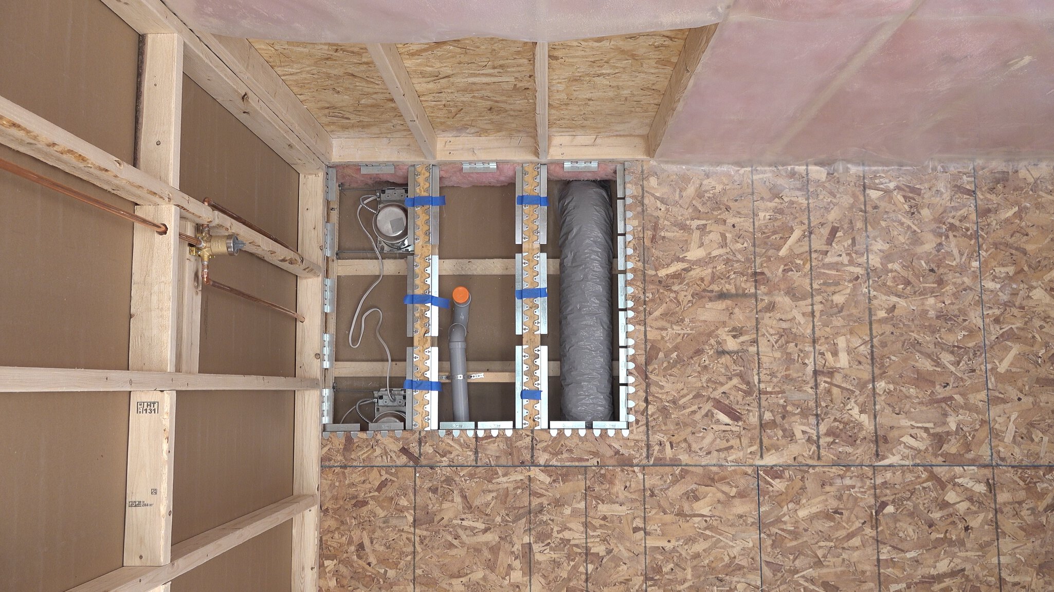
Dry fit brackets.

Note:
All corners must be supported by either a P or J bracket. It is best to lay out/plan the placement of all brackets before securing them in place.

P-Brackets

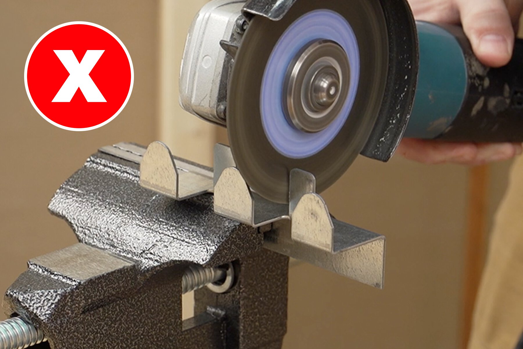
Do not cut P-brackets
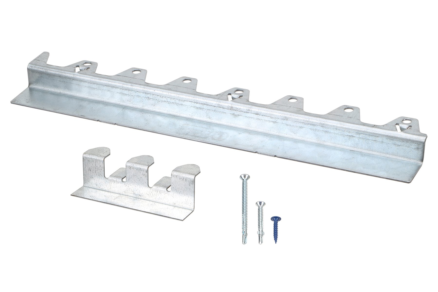
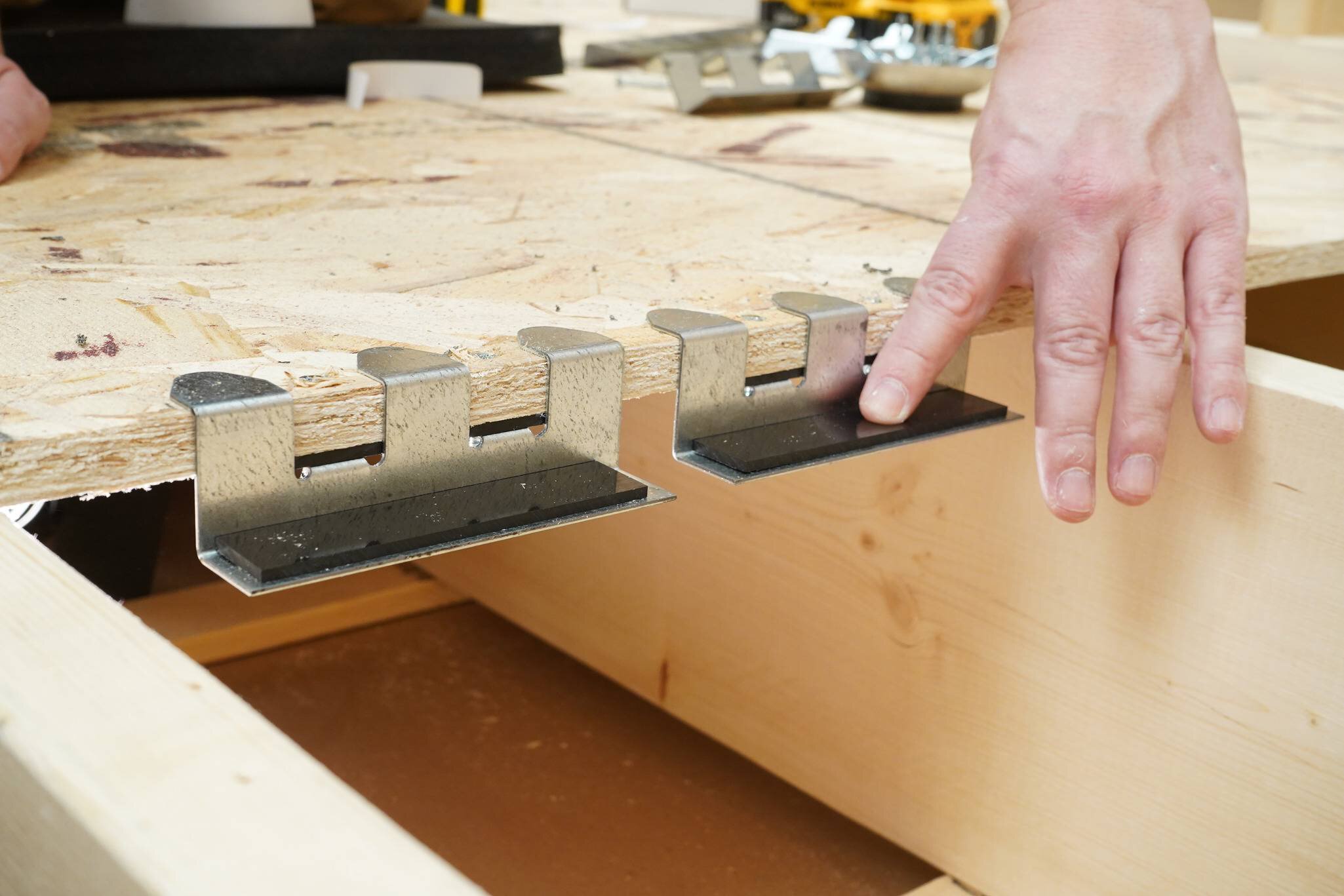
Lay out P-brackets according to the BRACKET PLACEMENT DIAGRAM.
Tap the P-bracket into place along the wall bottom plate using a scrap wood block and hammer.
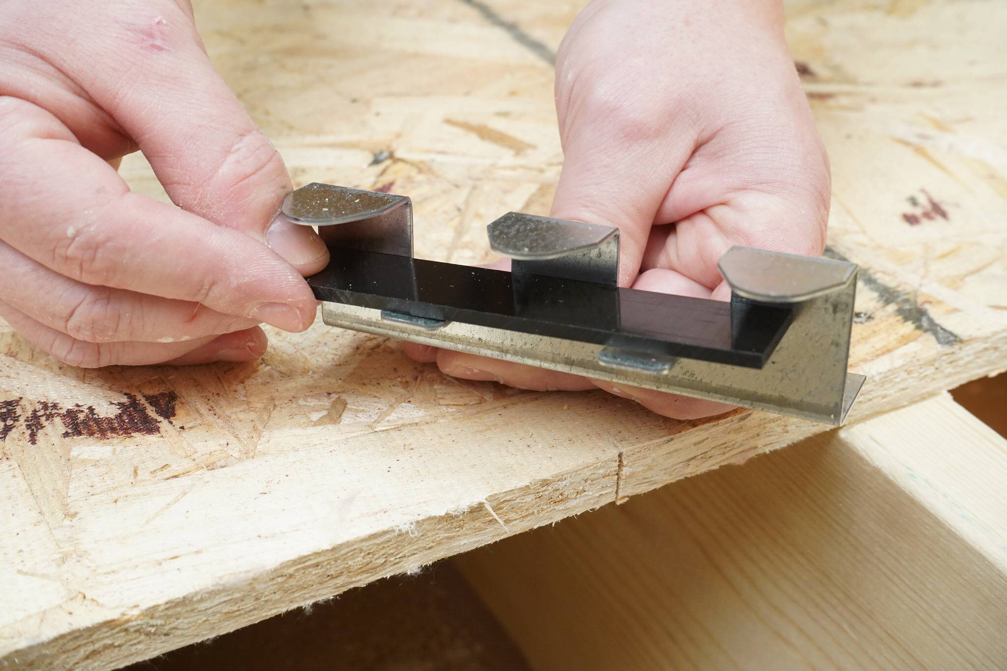
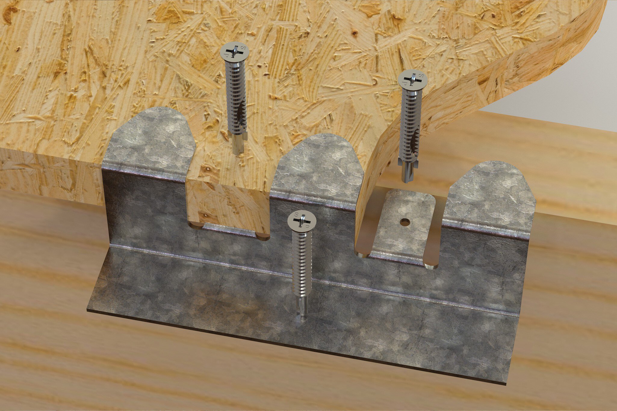
For 5/8" (16 mm) subfloors, clean the bracket and apply shims to the rectangular tabs, and insert the ledge.

J-Brackets

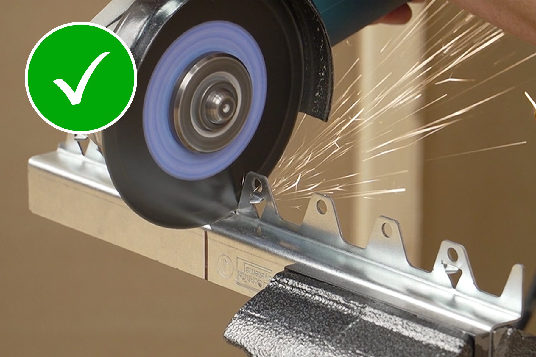
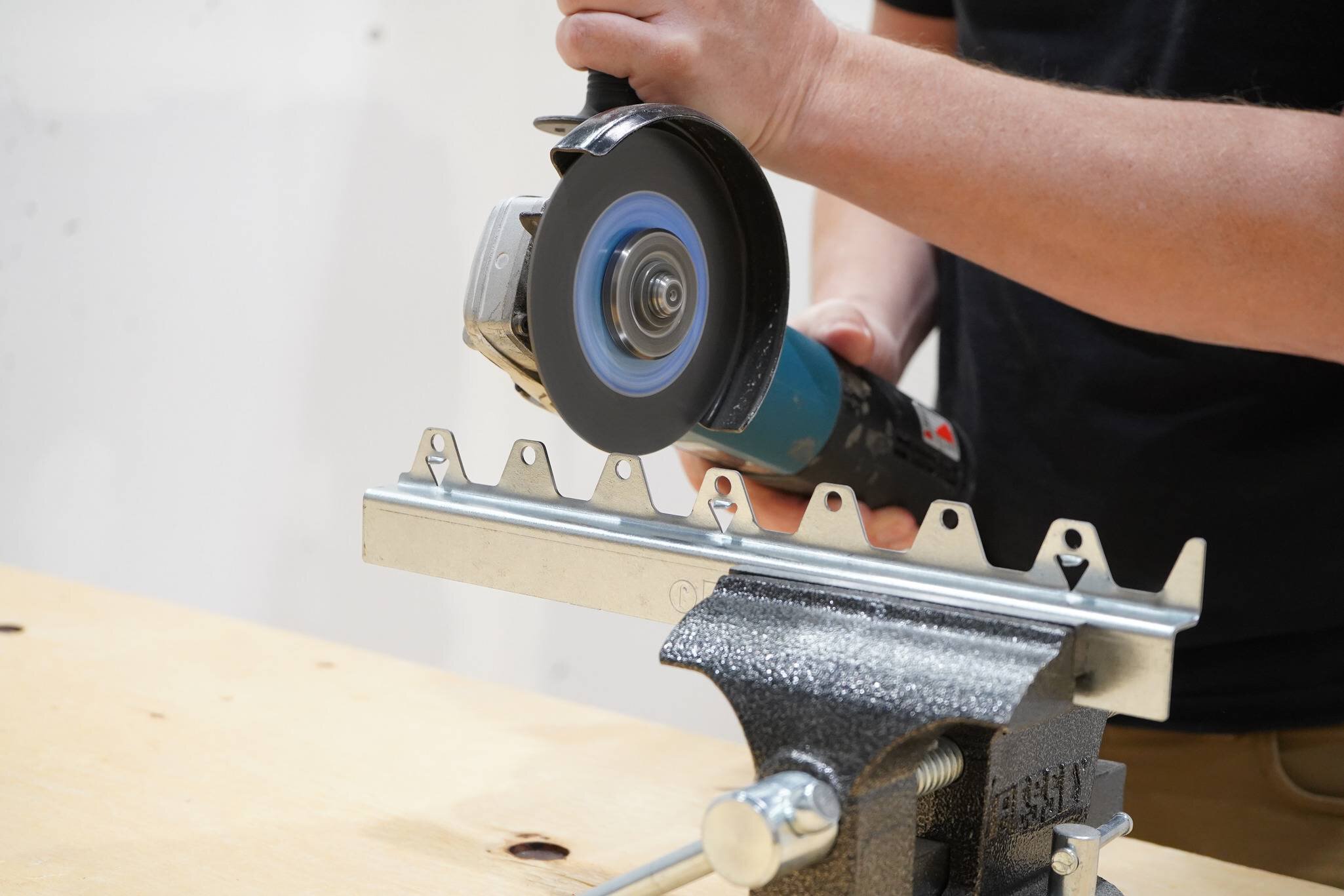
J-brackets may be cut to length
Cut J-brackets with appropriate tools (e.g., angle grinder with Schluter®-PROCUT-TSM).
Four screw holes MUST remain in each cut section that is used.
Lay out J-brackets according to the BRACKET PLACEMENT DIAGRAM.
If there is blocking in your floor cavity, use J-brackets on both sides, and ensure corners are supported.
9a

Attach brackets

Attach P-brackets
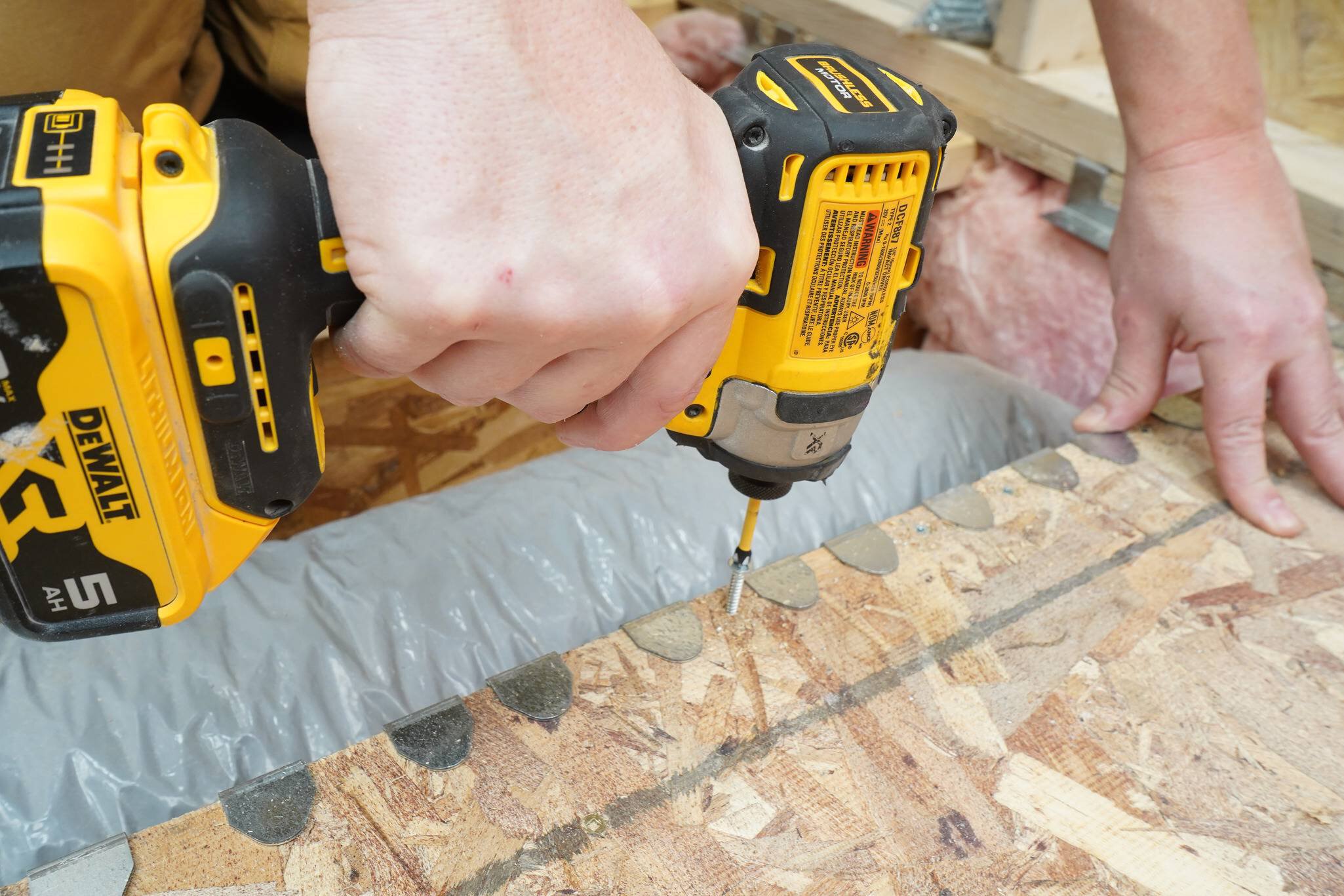
Pre-drilling recommended (*See Planning step 3.)
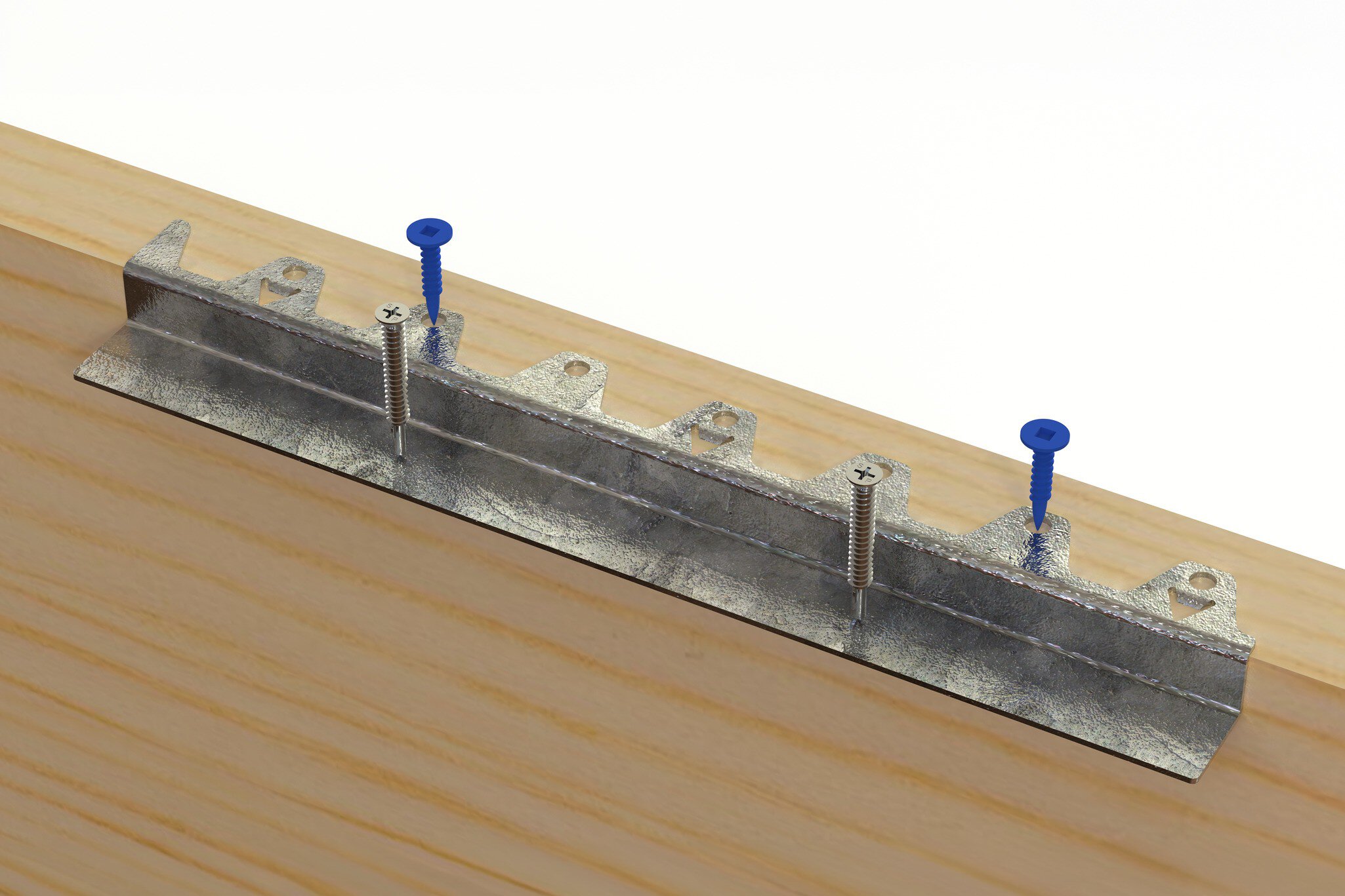
Secure P-brackets to the subfloor with two 1-5/8" (41.2 mm) wood-to-metal screws 1/2" (12.7 mm) from the edge. Screws pass through the subfloor into the rectangular tabs below.
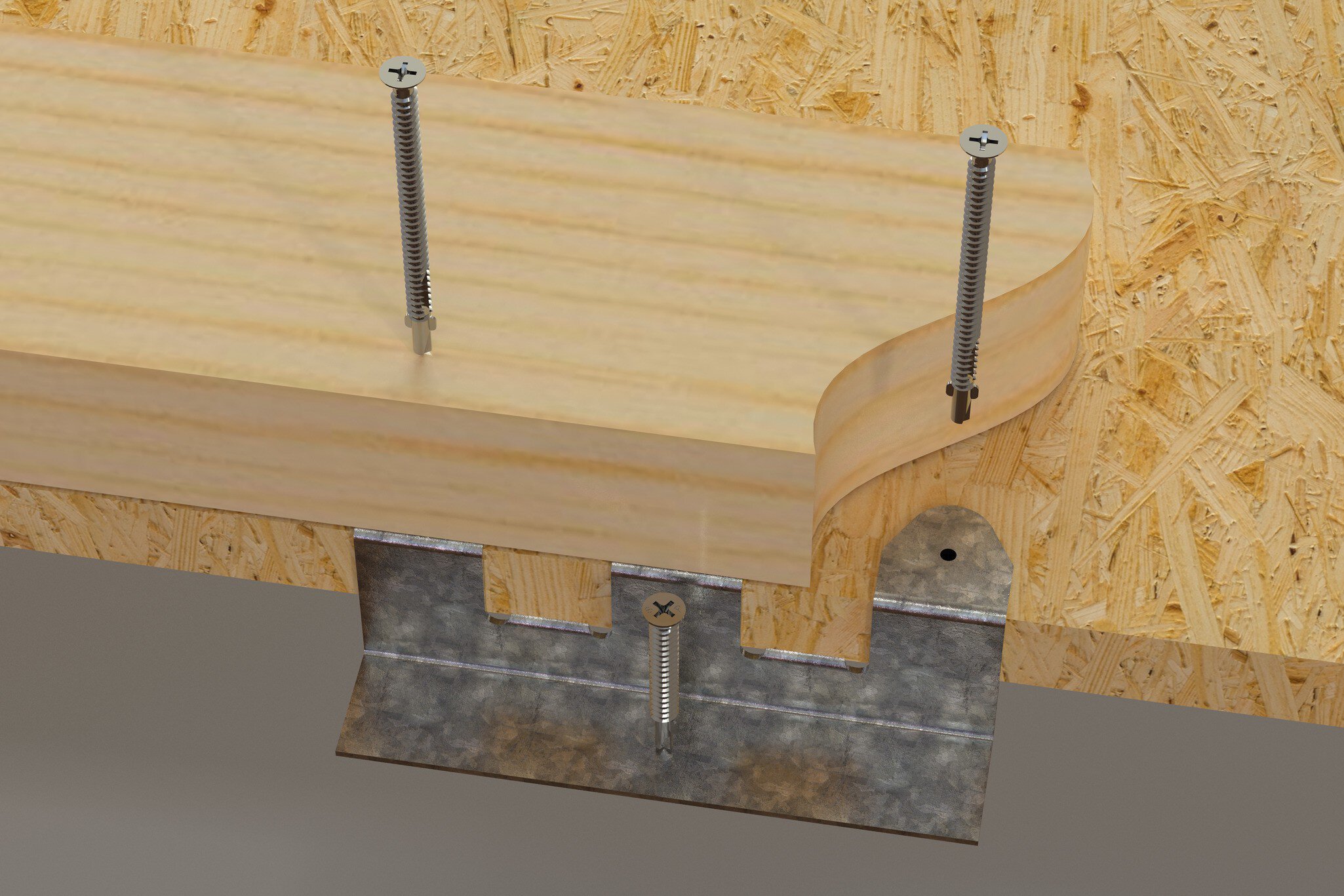
Secure P-brackets to the wall bottom plate using two 2-3/4" (70 mm) wood-to-metal screws 1/2" (12.7 mm) from the edge. Screws pass through the wall’s bottom plate into the center of any of the three top tabs.
Note:
All corners must be supported by either a P or J bracket. It is best to lay out/plan the placement of all brackets before securing them in place.
9b

Attach brackets

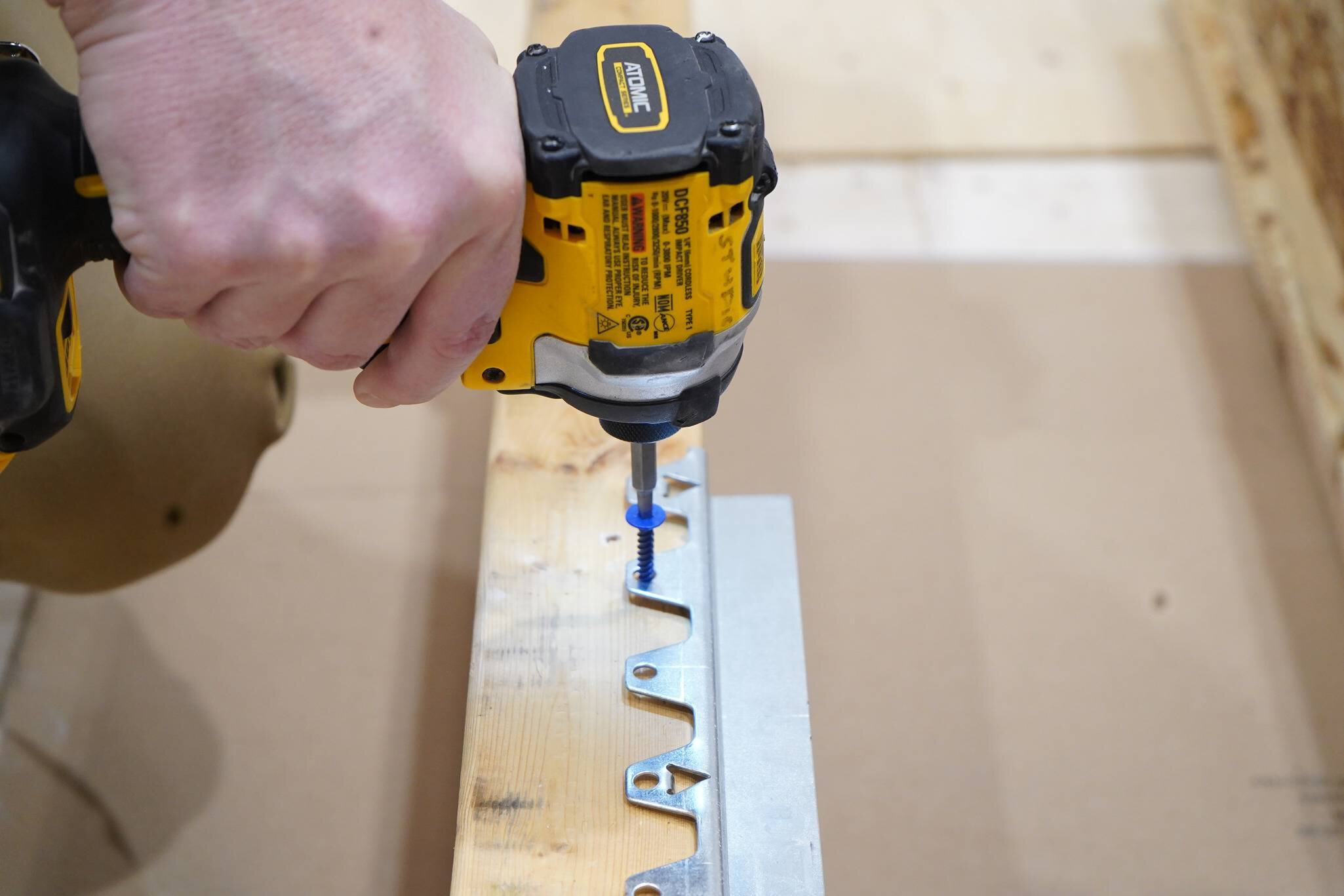
Attach J-brackets
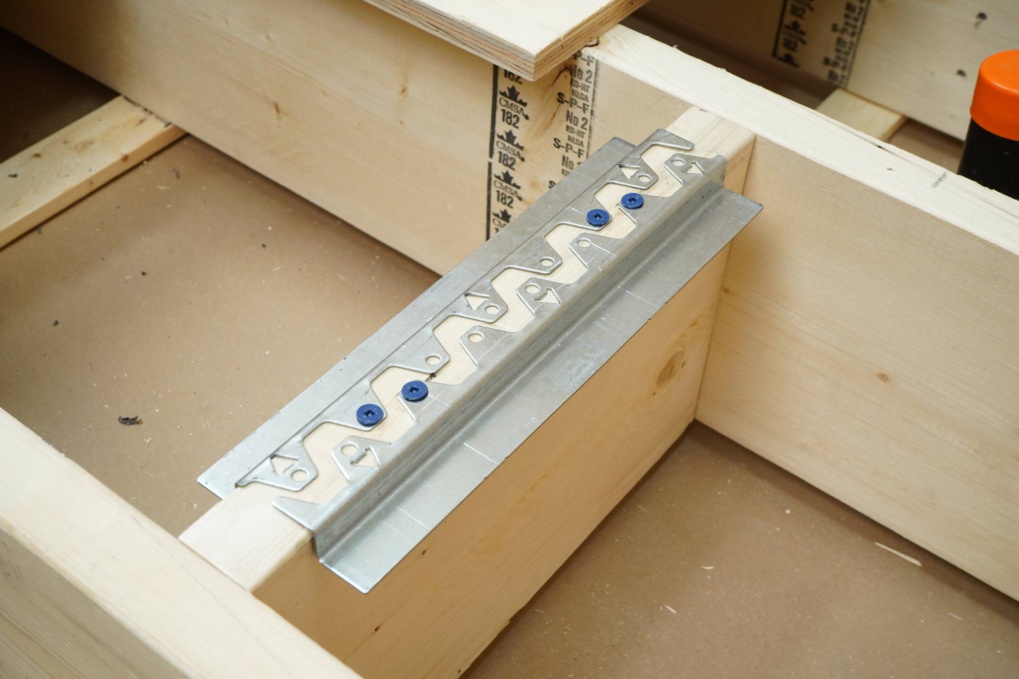
Gently hammer the J-brackets to drive in the tabs, then secure them with two 1 1/8" (29 mm) wood screws, keeping all in-line screws at least 4" (10 cm) apart.
10

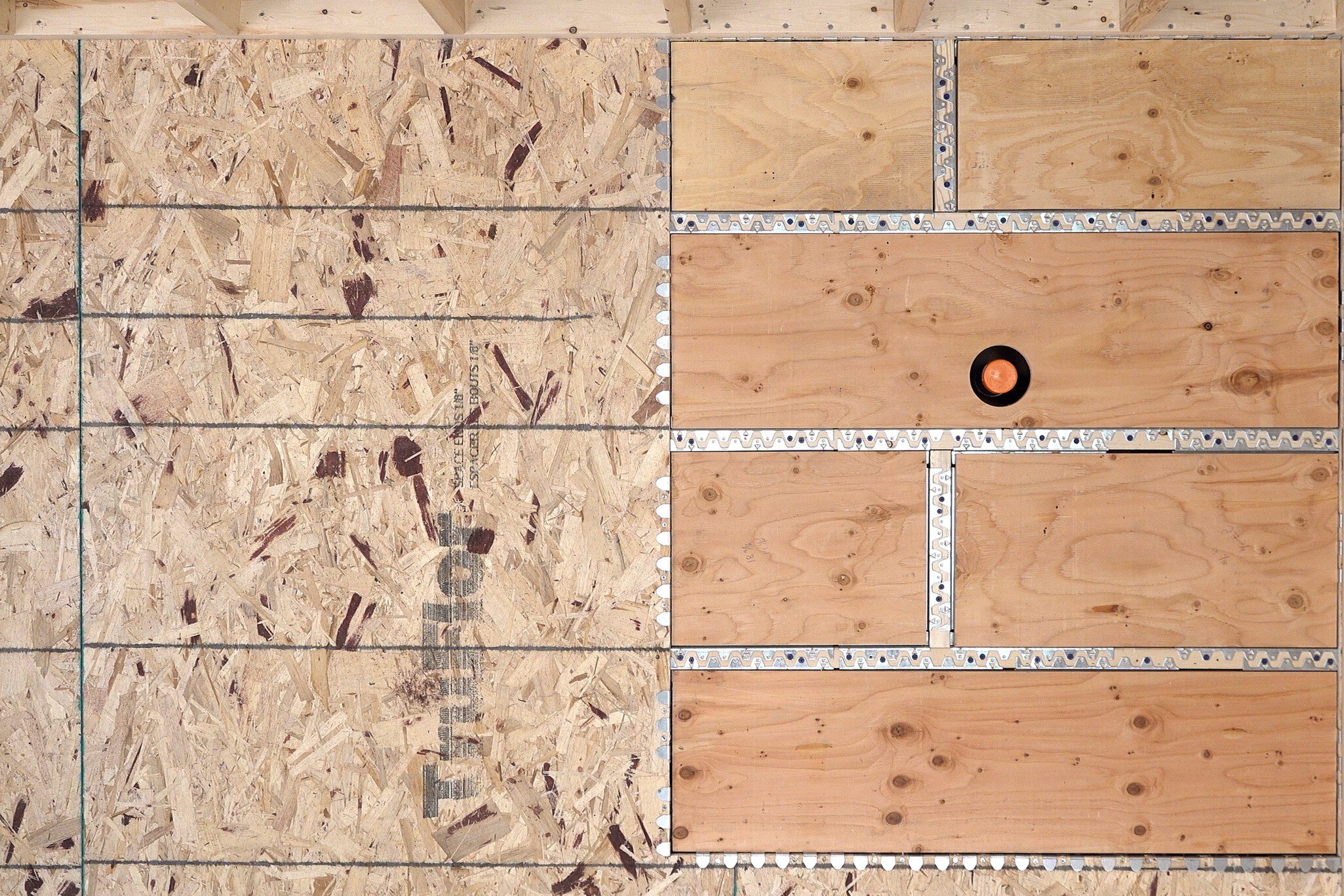
Measure, cut, and place plywood inserts
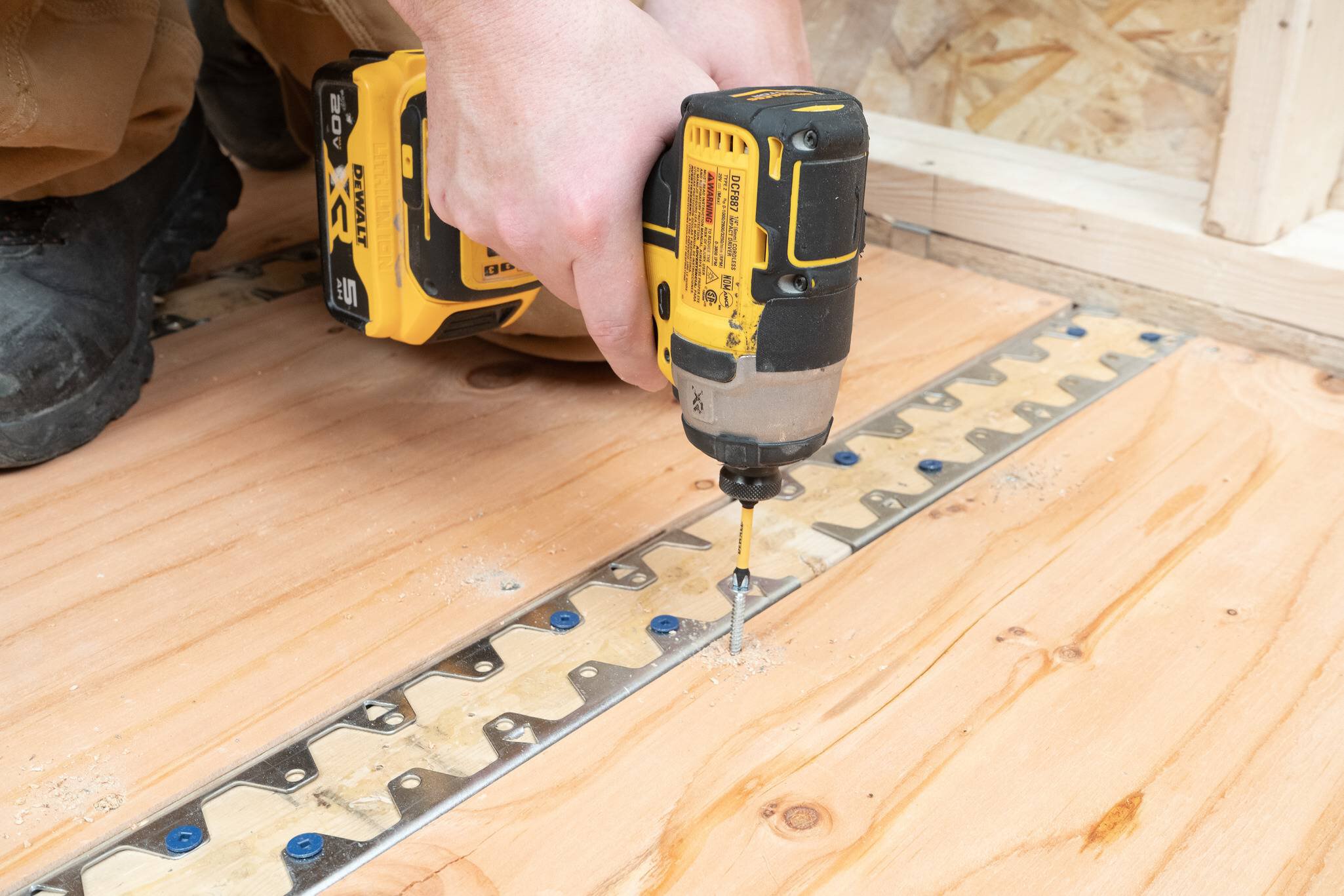
Inserts shall consist of a single piece of ¾" (19 mm) plywood, and shall be free of holes, damage, or defects, with cleanly cut edges and no blowouts.
Measure each opening between the brackets. Subtract ¼" for the Length and Width to allow for a 1/8" gap on all sides.
Manufacturers recommend installing plywood with the face grain perpendicular to supports. ERS testing has verified acceptable performance in all orientations; while perpendicular placement is preferred, panels may be installed in any direction to improve layout flexibility and reduce waste.
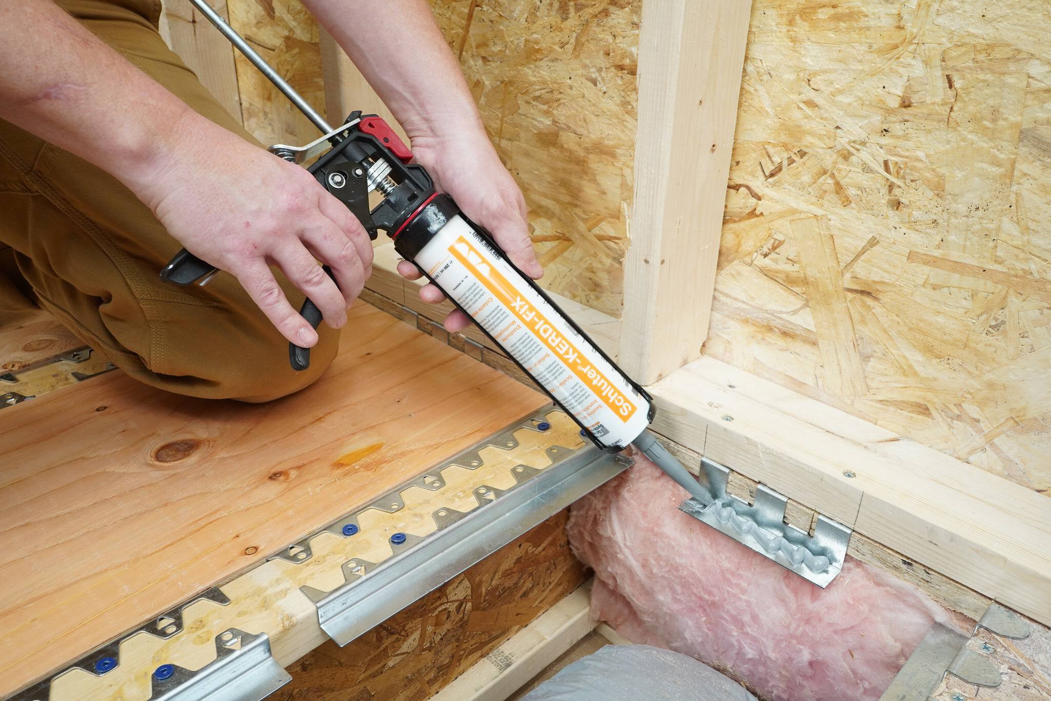
Apply Schluter®-KERDI-FIX or (non-expanding) construction adhesive to all bracket ledges before setting inserts in place.
Note:
OSB may NOT be used for the inserts.
11

Fasten inserts to the brackets

Pre-drilling recommended (*See Planning step 3.)
Fasten plywood inserts in place using the provided 1-5/8" (41.2 mm) wood-to-metal screws 1/2" (12.7 mm) from the edge. One screw per P-bracket and two screws, evenly spaced, per J-bracket.
Note:
If you choose not to predrill, favor high speed, low pressure until the screw cuts into the metal.
12

Reinstall/ install wallboard

13

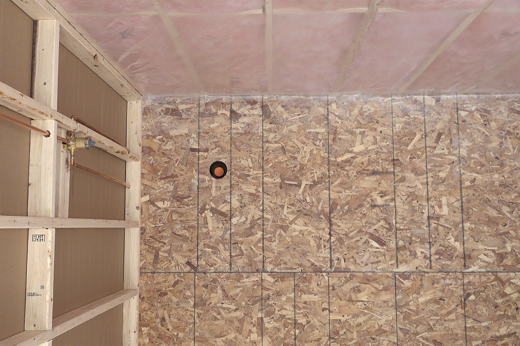
Drill/cut the core hole for the Schluter®-KERDI-DRAIN
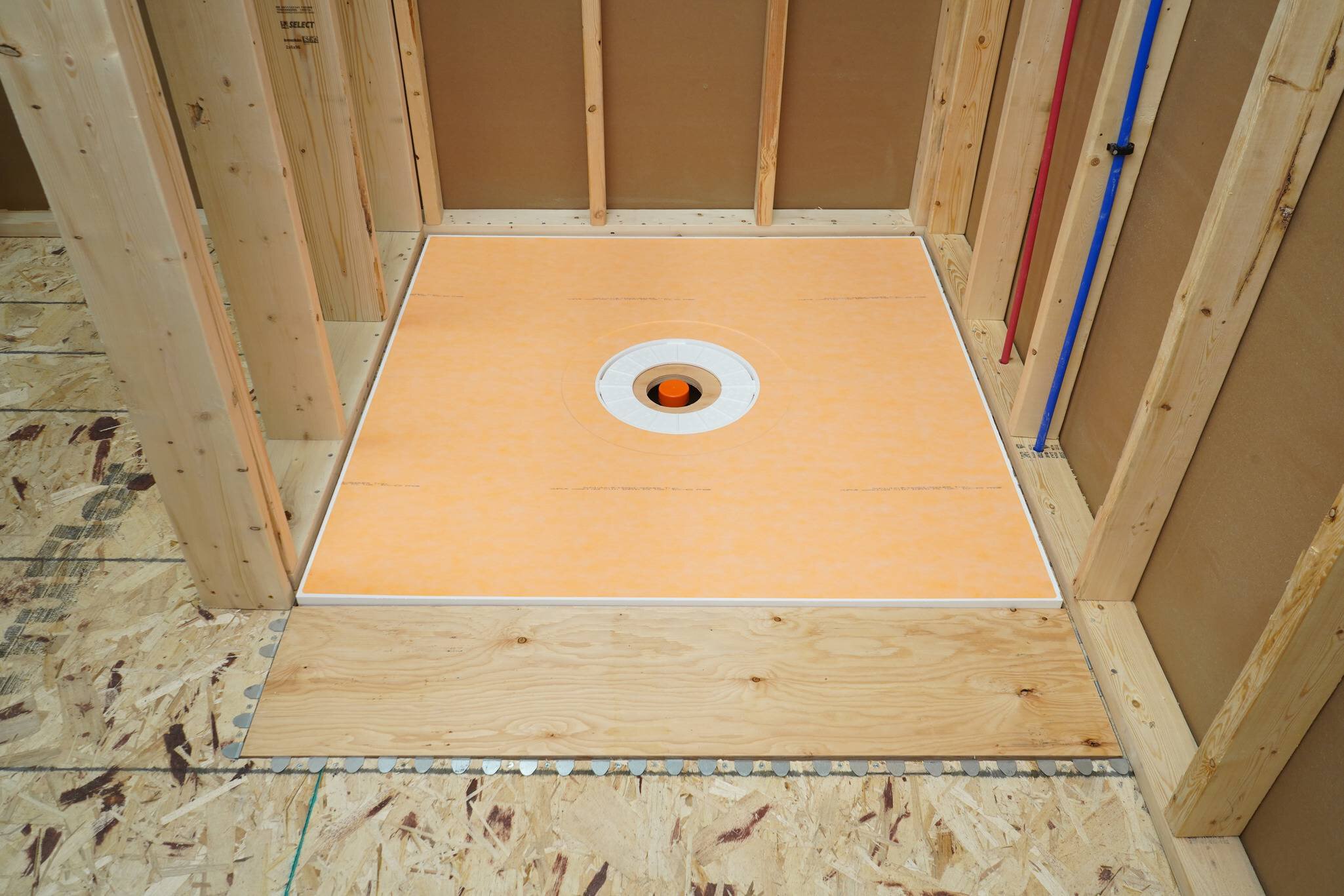
Follow all recommendations and instructions for the Schluter®-KERDI-DRAIN to be installed.
Note:
Limit the diameter of the hole to 5" (12.5 cm) maximum to ensure proper support for the tile assembly.
14

Measure, cut, and attach the filler piece
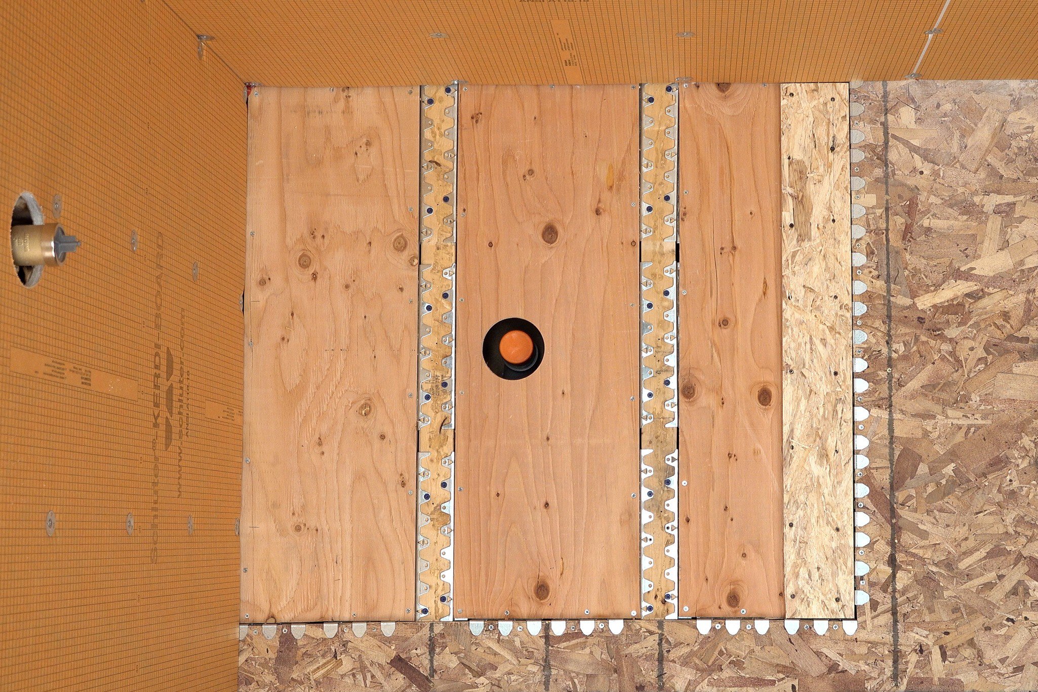
Place the shower tray, then measure and cut a filler piece for the remaining recessed section.
For 3/4" (19 mm) subfloor - use 5/8" (16 mm) plywood or OSB.
For 5/8" (16 mm) subfloor - use 1/2" (12.7 mm) plywood or OSB.
Attach filler pieces.
Treat filler pieces as an additional layer of subfloor sheeting. Follow the manufacturer's recommendation for plywood or OSB and local codes.
Avoid driving screws into bracket ledges (keep 1" (2.5 cm) from the edge).
15

Waterproof the walls

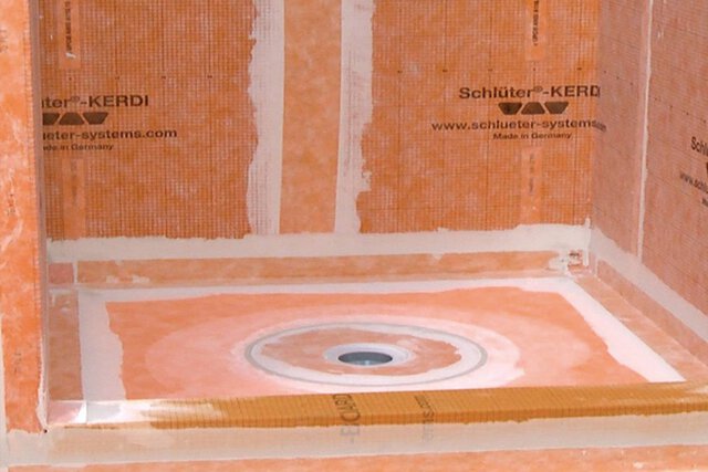
It is recommended to waterproof the walls at this point, then install the tray. The order is up to the installer's discretion.
Refer to the Schluter®-Shower System Installation Handbook for more information.
16

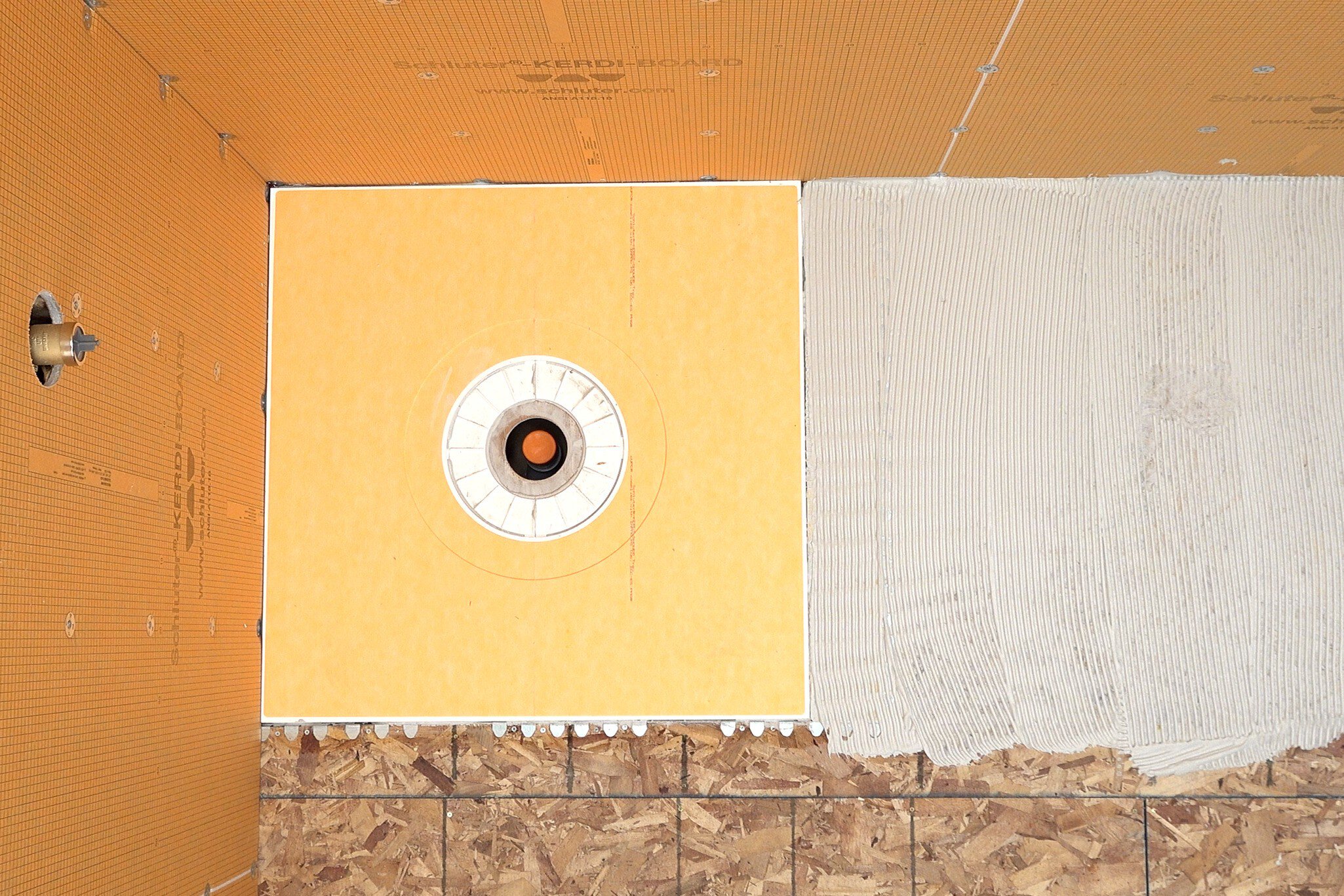
Following the Schluter®-Shower System Installation Handbook, check for level and install the tray in the recessed section.
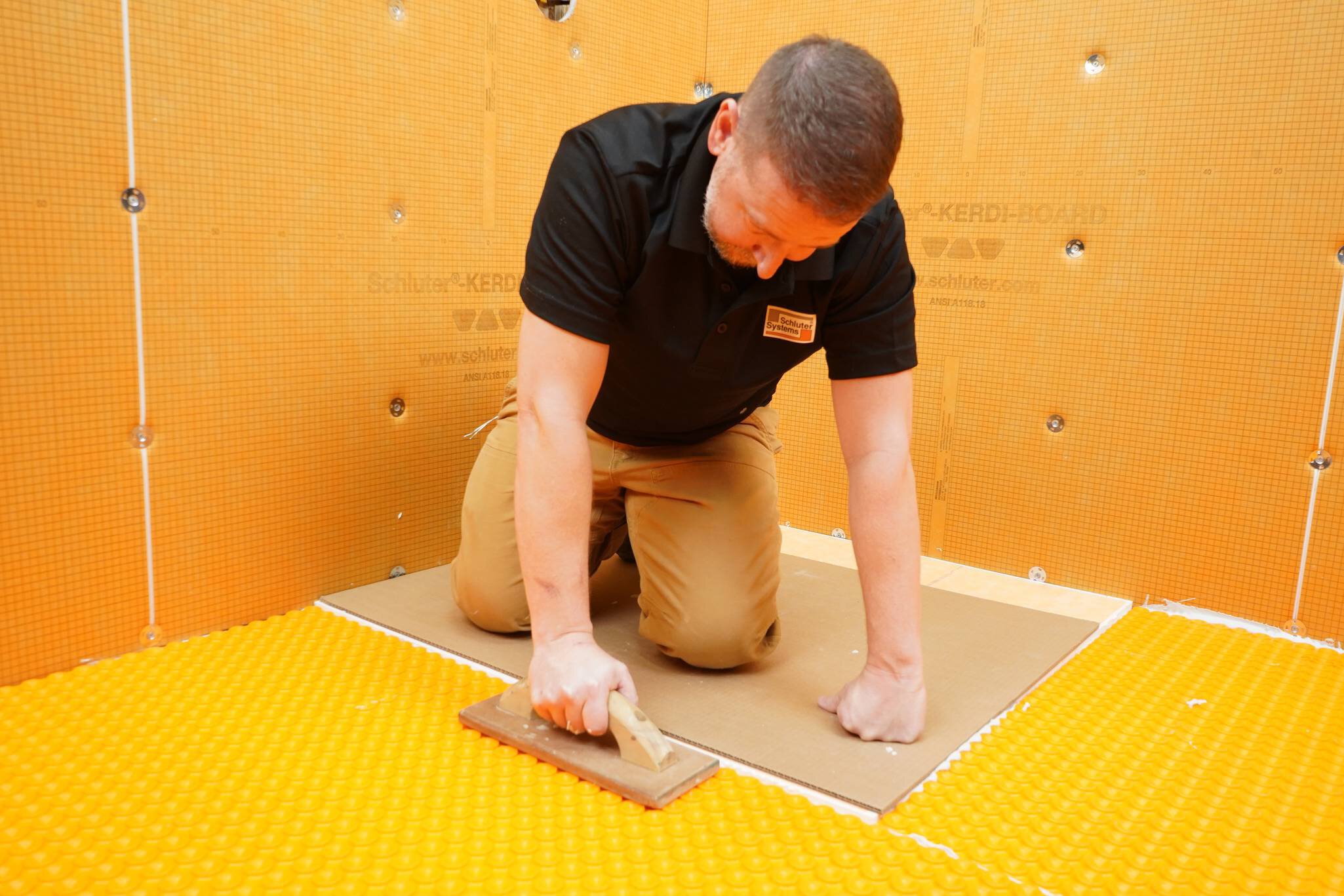
17

Install Schluter uncoupling membrane (i.e., DITRA, DITRA-HEAT, etc.) flush with the perimeter of the tray.
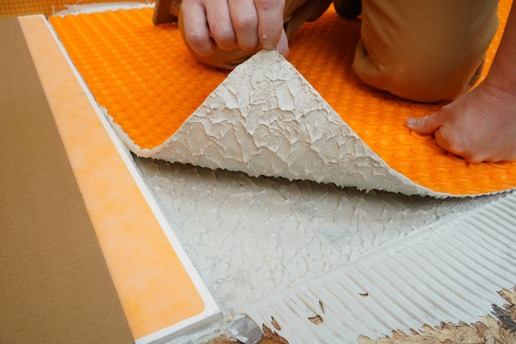
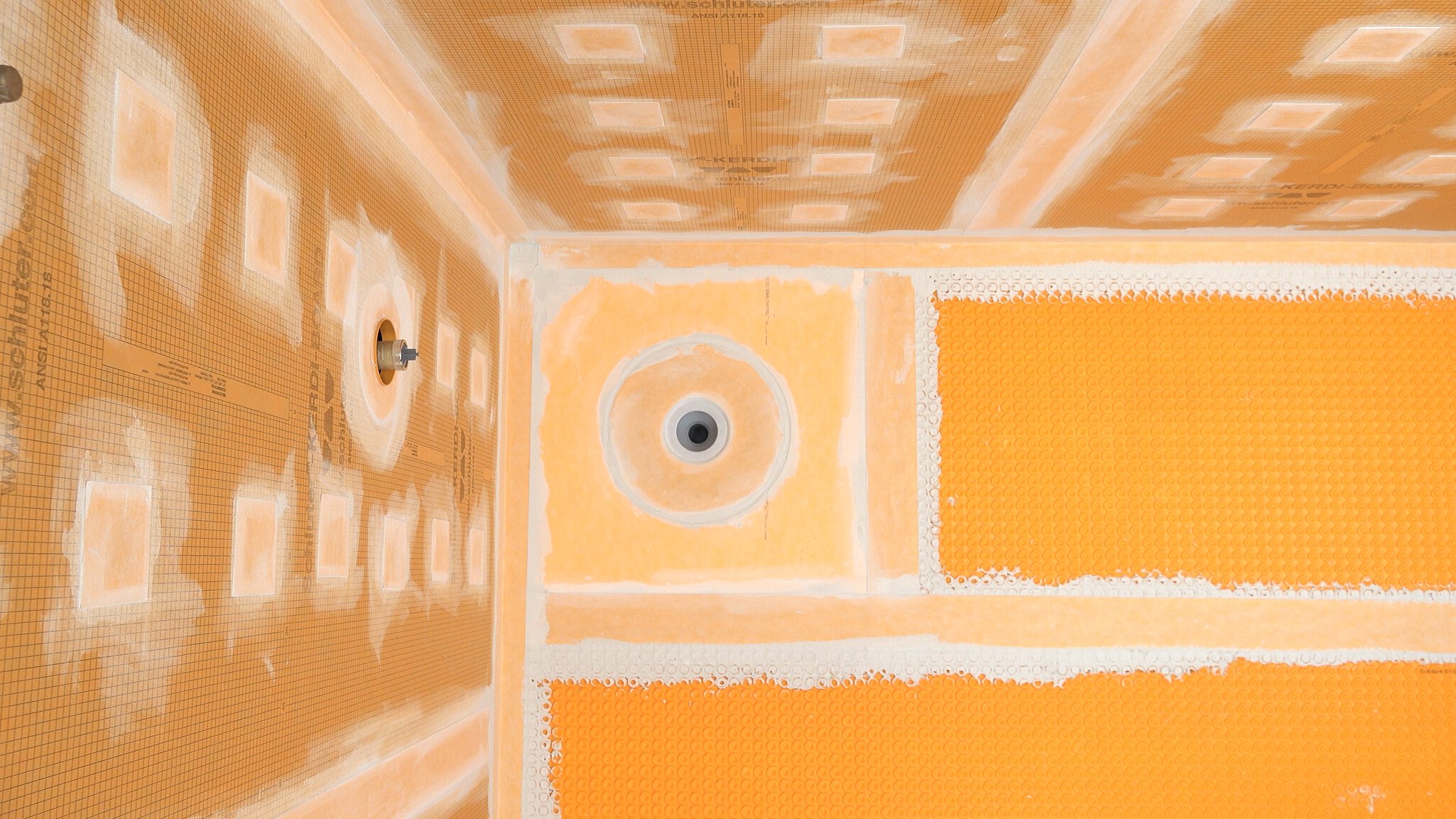
Use Schluter membranes, patching compound, floor self-leveler, or the appropriate additional underlayment/sheeting as needed.
The uncoupling membrane should be installed abutted to and flush with the tray. Take special care to ensure appropriate coverage over bracket tabs.
Reference the COMPONENT THICKNESS table for FRS and common associated component thicknesses.
18

Complete waterproofing

Note:
Industry guidelines recommend waterproofing a minimum of 1 ft (30.5 cm) beyond the shower area for curbless showers.
Follow all requirements outlined in the Schluter®-Shower System Handbook.
Because wet areas and dry areas are not clearly defined in curbless showers, Schluter recommends that the bathroom be sufficiently protected against water and moisture. Use the appropriate Schluter waterproofing products in all floor areas subject to water exposure (i.e., wet area and drying area).
Seams and floor-to-wall connections shall be sealed with KERDI-BAND.
19

Perform Water Test (Strongly Recommended)

Before setting tile to verify a successful installation:
Wait a minimum of 24 hours after the membrane installation is complete to allow for final set of thin-set mortar and ensure waterproof performance of seams and connections.
Refer to local plumbing codes for any specific requirements in your area.
For curbless showers, a temporary dam must be provided at the threshold to perform the water test.

CAPILLARY BREAK RECOMMENDATION

Consider installing a capillary break to reduce the risk of moisture migration from the curbless shower to the drying area. Refer to the TCNA Handbook for Ceramic, Glass, and Stone Tile Installation for more information.

Schluter®-KERDI-DRAIN

Schluter®-
KERDI-DRAIN

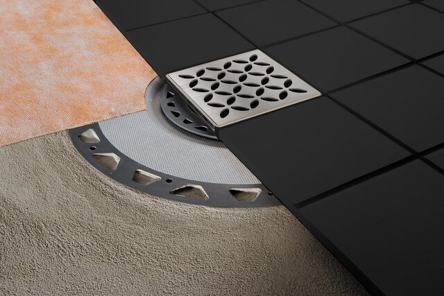
Point drain with integrated bonding flange

Schluter®-KERDI-SHOWER-T/-TS/-TT

Schluter®-
KERDI-SHOWER-T/-TS/-TT

Prefabricated sloped shower tray

Schluter®-KERDI

Schluter®-
KERDI

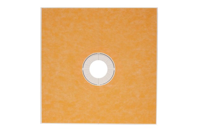
Bonded waterproofing and vapor-retardant membrane

Schluter®-KERDI-FIX

Schluter®-
KERDI-FIX

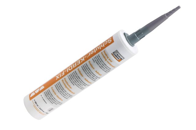
Single-component sealing and bonding compound

Schluter®-DITRA & DITRA-XL

Schluter®-
DITRA & DITRA-XL

Uncoupling and waterproofing membrane

Schluter®-DITRA-HEAT

Schluter®-
DITRA-HEAT

Uncoupling membrane for DITRA-HEAT-E-HK electric floor heating cables