Installing the Schluter®-KERDI-DRAIN-H Point Drain with Horizontal Outlet
Para conocer las especificaciones y las instrucciones completas de instalación de las aplicaciones de ducha, consulte el Manual de instalación del Sistema de ducha Schluter®.
There are 2 parts to installing KERDI-DRAIN: The flange and the grate.
Installing a stainless steel KERDI-DRAIN flange in a commercial application? Click here.
Installing the flange
The KERDI-DRAIN flange can be installed in conjunction with the KERDI-SHOWER-T/-TS/-TT prefabricated shower trays or with a mortar bed. Select the video that pertains to your application below:
Preparation
The KERDI-DRAIN flange can be installed in conjunction with the KERDI-SHOWER-T/-TS/-TT prefabricated shower trays or with a mortar bed. Select the video that pertains to your application below:
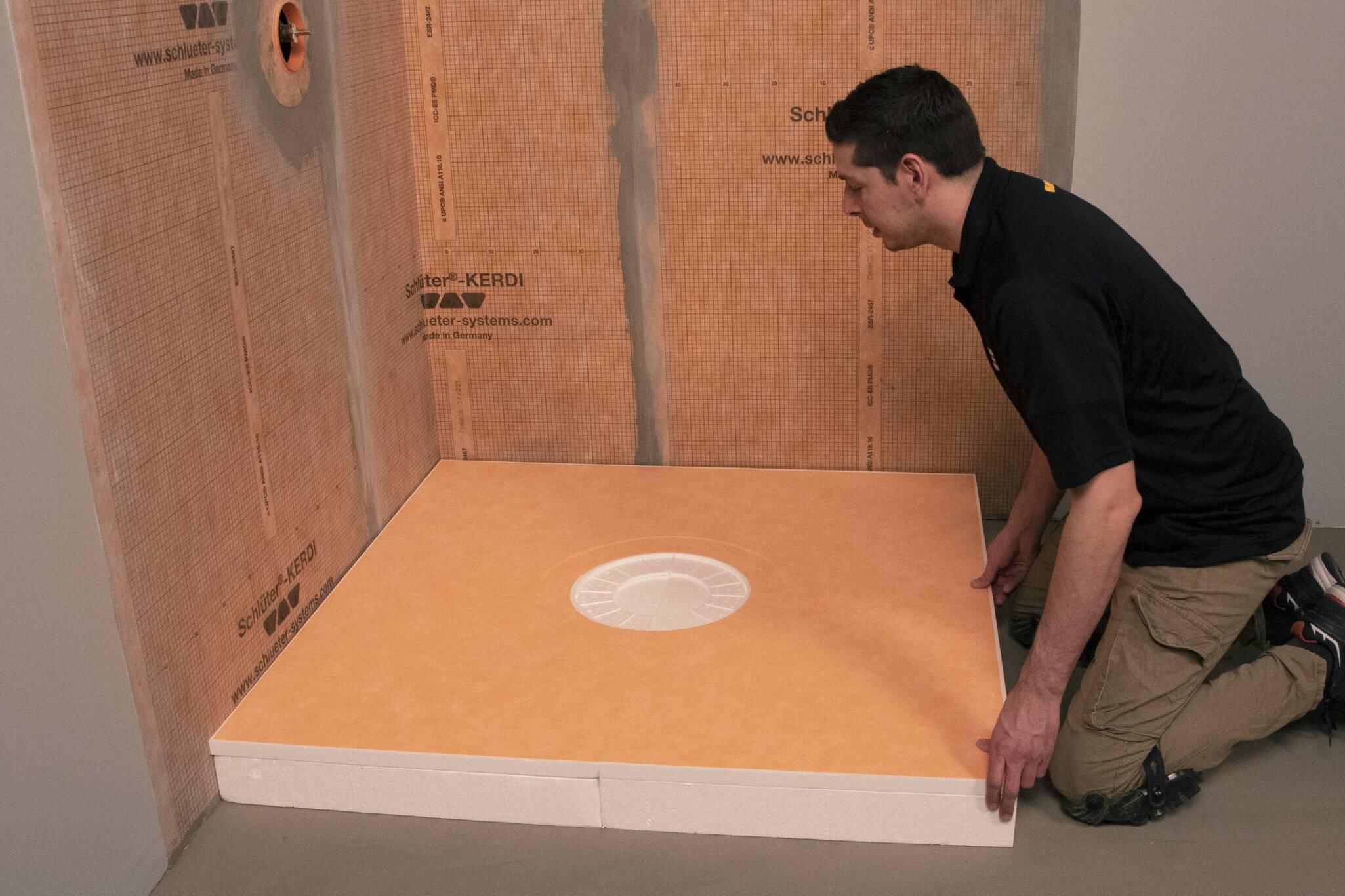
Dry fit the Schluter-KERDI-SHOWER-CB compensation board and KERDI-SHOWER tray. If necessary, cut the tray and compensation board to size.
Take measurements for the drain flange and ABS/PVC outlet pipe locations.
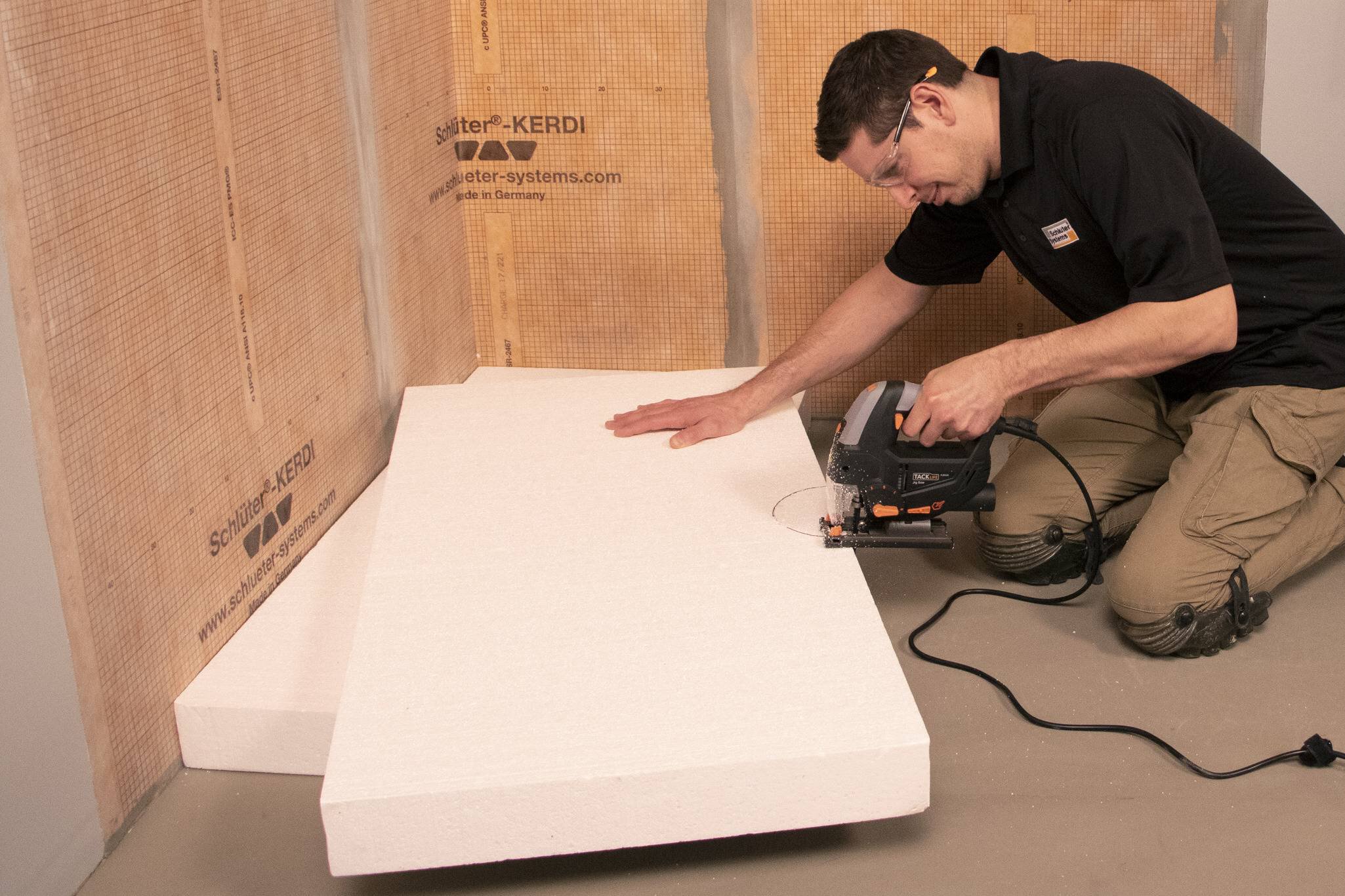
Mark and cut compensation board for the KERDI-DRAIN-H flange opening using the template provided (maximum 5" (125 mm) diameter).
Mark and cut a 2-3/4" (70 mm) – 3" (76 mm) maximum wide slot for the ABS/PVC outlet pipe. Do not exceed the maximum to ensure proper tile support.
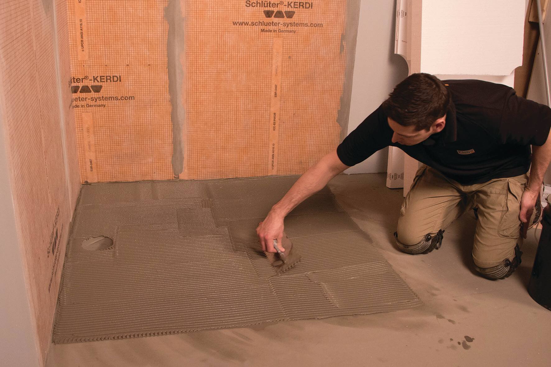
Apply Schluter SET®, ALL-SET®, FAST-SET®, or unmodified thin-set mortar to the substrate using a 1/4" x 3/8" (6 mm x 10 mm) square- or U-notched trowel.
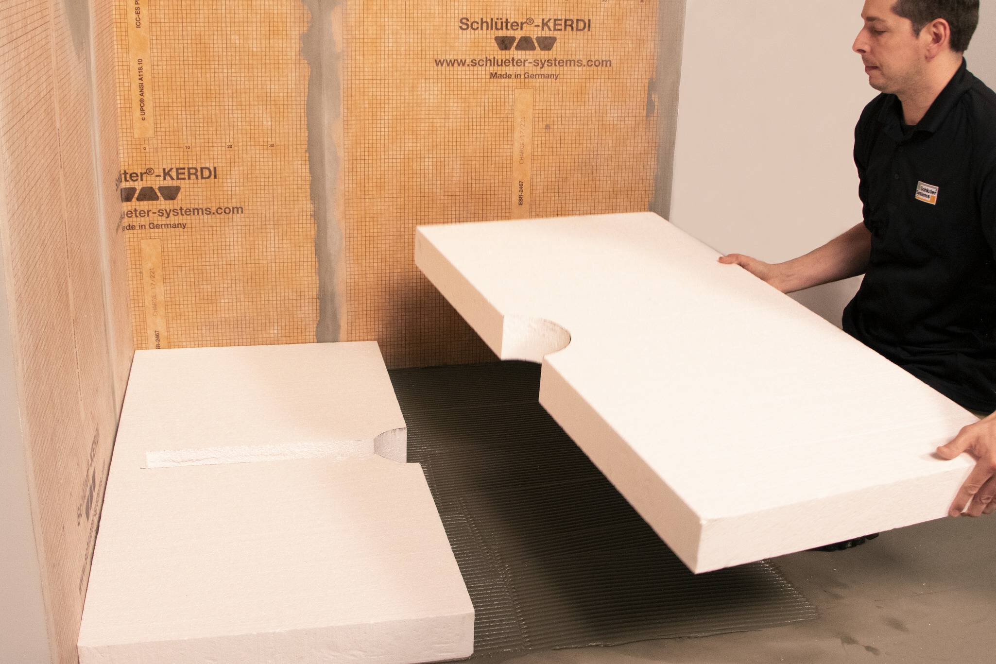
Place the KERDI-SHOWER-CB compensation board and solidly embed in the mortar.
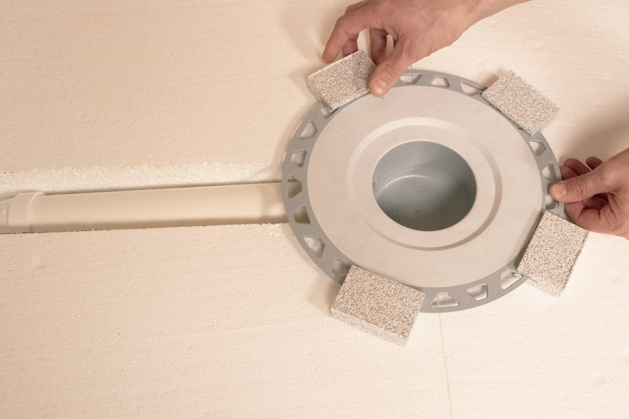
Dry fit the plumbing components. Measure and cut a section of pipe to connect KERDI-DRAIN-H to the odor trap using the detachable center section of the tray, or foam spacers included with the drain, as a spacer.
Proper slope MUST be maintained to ensure adequate drainage. Prepare the pipe and KERDI-DRAIN-H with cleaner, primer, and ABS or PVC cement per the solvent cement manufacturer’s installation instructions and connect.
Note: Schluter Systems strongly recommends a leak test be performed on the connection between the drain and the waste line prior to continuing with the remainder of the installation whenever possible.
Refer to local plumbing/or building codes for any specific requirements in your area.
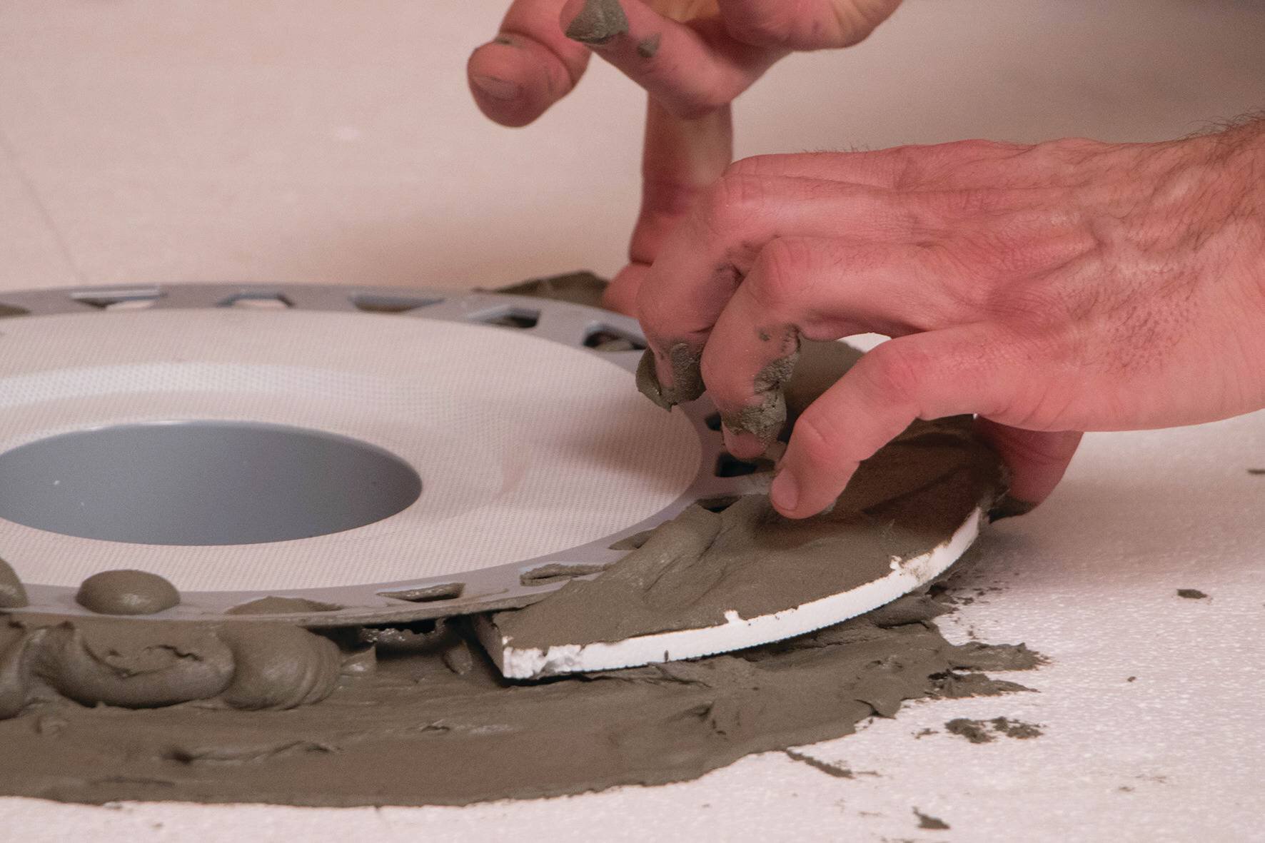
Apply Schluter SET, ALL-SET, FAST-SET, or unmodified thin-set mortar to the KERDI-SHOWER-CB compensation board and to the top and bottom of the detached center section of the KERDI-SHOWER tray.
Slide the center section into place below the drain to ensure solid and uniform support of the bonding flange.
Note: If mosaic tiles (tile format less than 2" x 2" (50 mm x 50 mm)) will be used on the shower tray, the shower tray seam is located over the pipe cut-out, or the tray will be exposed to heavy loads the slot in the compensation board must be filled with a sand mortar or dry-pack to ensure proper support of the tile assembly.
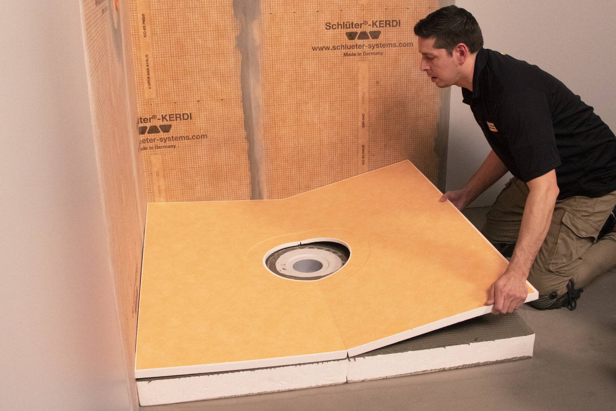
Apply Schluter SET, ALL-SET, FAST-SET, or unmodified thin-set mortar to the top of the KERDI-SHOWER-CB compensation board using a 1/4" x 3/8" (6 mm x 10 mm) square- or U-notched trowel.
Place the KERDI-SHOWER tray and solidly embed in the mortar.
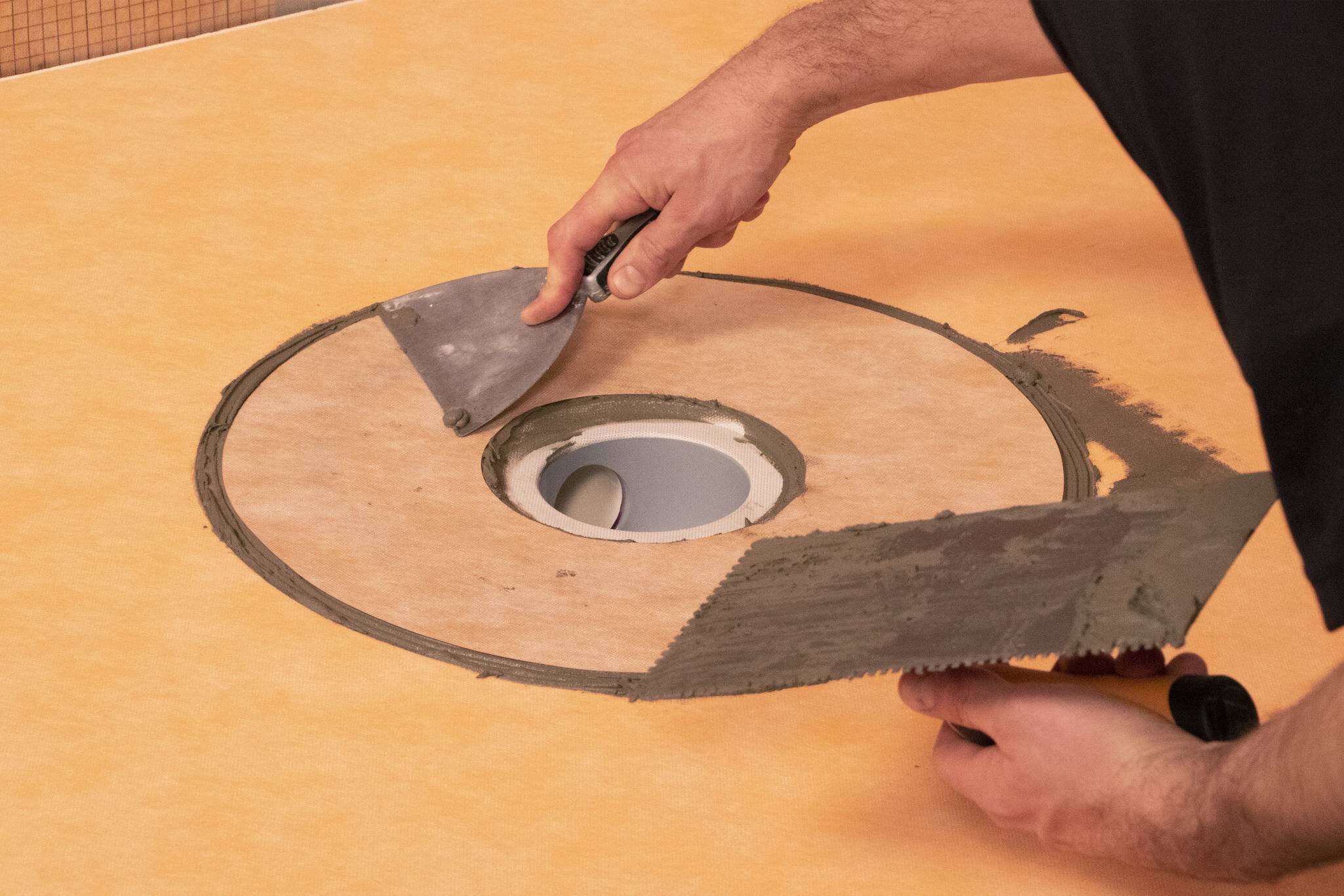
Apply Schluter SET, ALL-SET, FAST-SET, or unmodified thin-set mortar to the bonding flange and recess area in the tray with a 1/4" x 3/16" (6 mm x 5 mm) V-notched trowel or the KERDI-TROWEL.
The thin-set mortar must be mixed to a fairly fluid consistency, but still able to hold a notch.
Embed the KERDI membrane collar in the bond coat and work the membrane onto the KERDI-DRAIN bonding flange and shower base to ensure full coverage and remove air pockets.
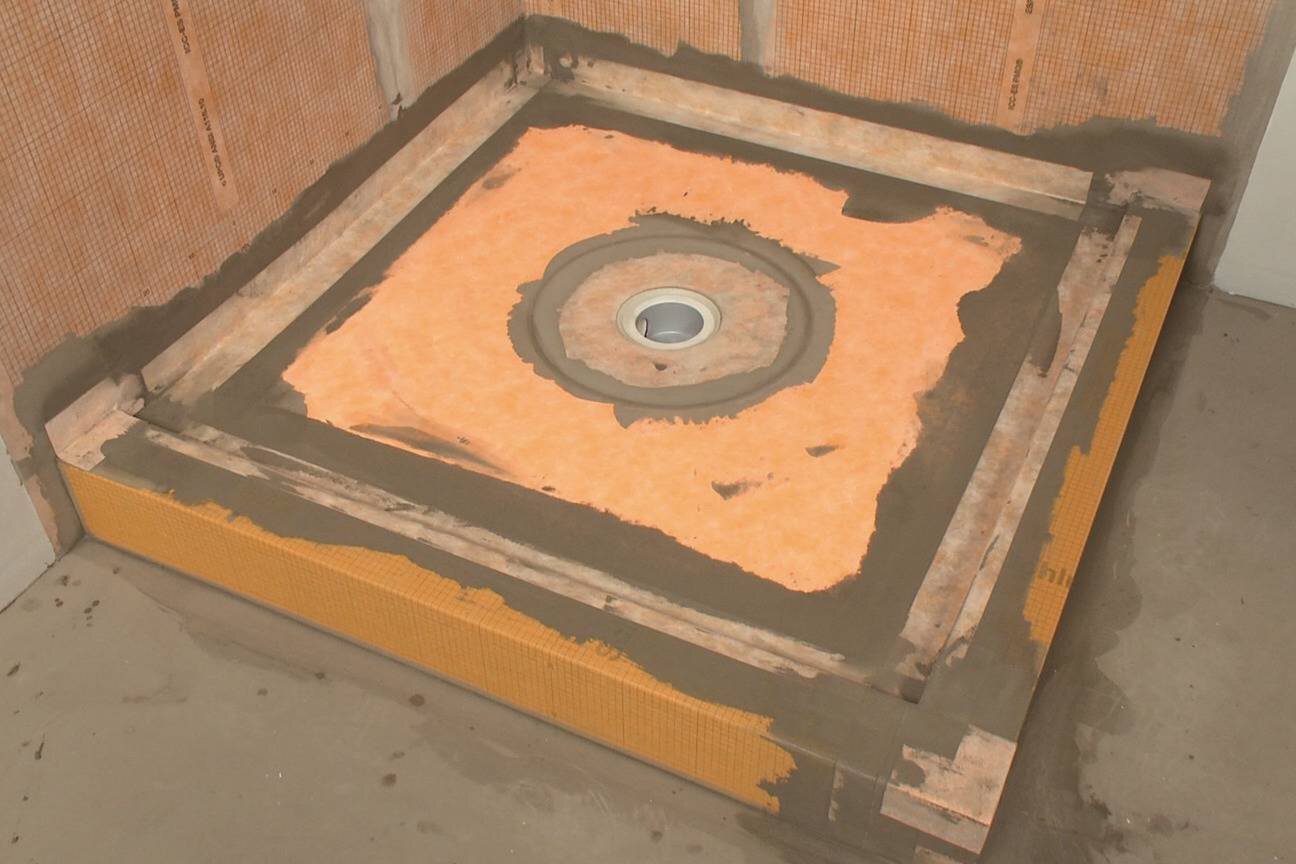
Seal inside corners by abutting adjacent sheets and installing KERDI-BAND with Schluter SET, ALL-SET, FAST-SET, or unmodified thin-set mortar, centered over the joint.
Install KERDI-KERECK prefabricated waterproofing corners at all inside and outside corners. When using the KERDI-BOARD-SC curb, seal the curb to the base and walls using KERDI-KERECK and KERDI-BAND.
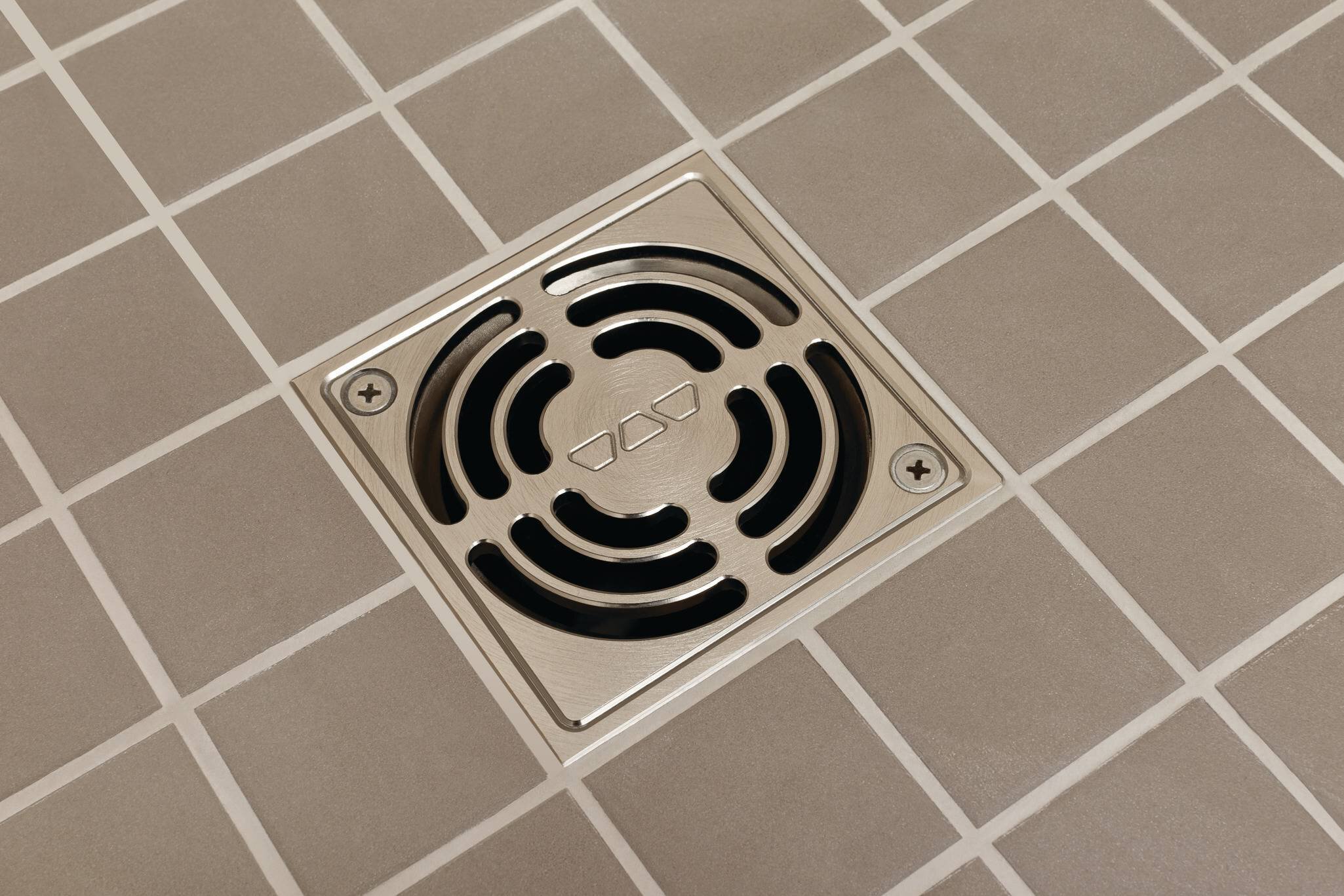
Installing the grate
Two types of grates are available for KERDI-DRAIN: metal grates with a frame or a frameless tileable grate.
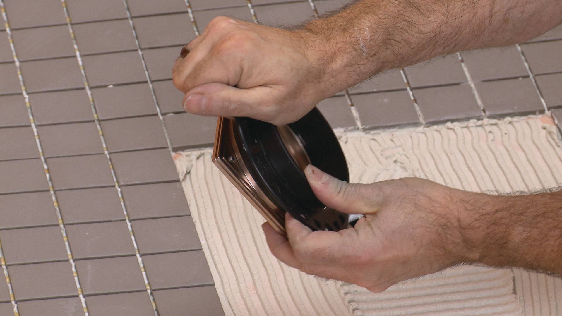
Place the height adjustment collar inside the lateral adjustment ring and snap the grate into place. Note: For the 6" (150 mm) grates, the height adjustment collar is integrated with the grate.
For the residential adaptor kit, there is no lateral adjustment ring.
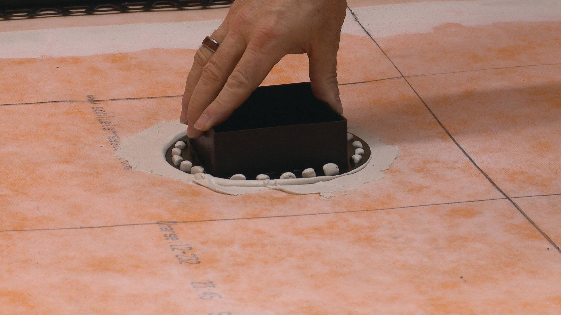
Fill the step in the bonding flange with thin-set mortar and back-butter the underside of the grate to ensure full support.
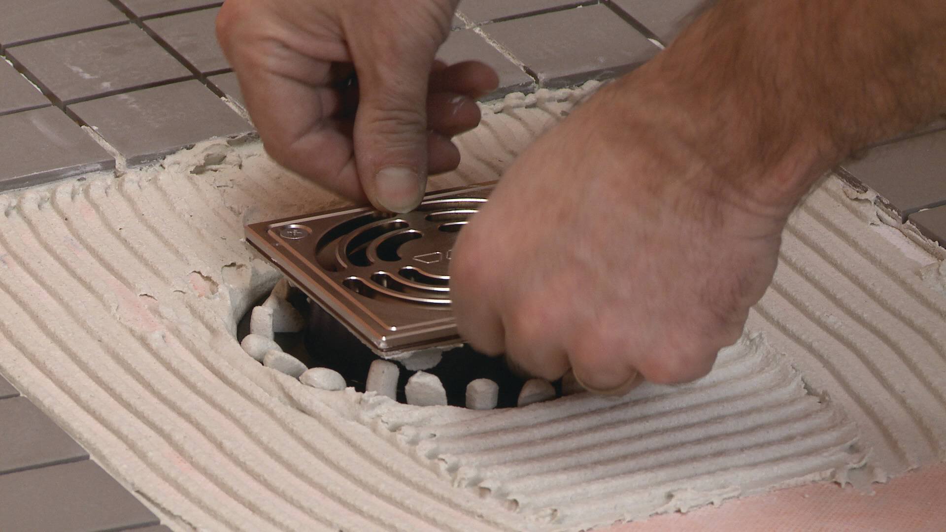
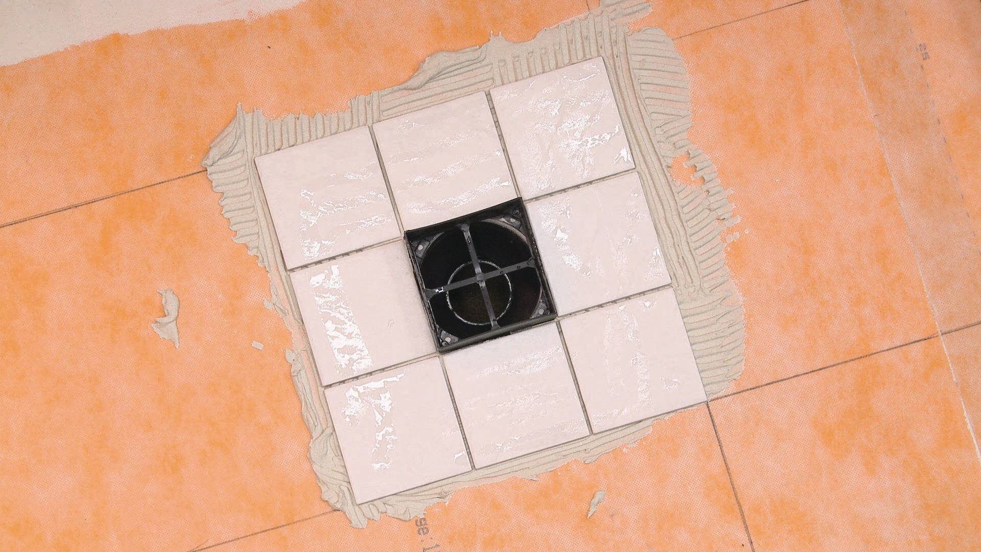
Place the assembly into the mortar and install the surrounding tiles, ensuring full coverage.
Position the grate to match the joint pattern of the tile covering and press flush with the tile surface. Remove all excess setting material immediately.
Note: Protect the visible surface of the grate from contact with setting and grouting materials. In particular, anodized aluminum is sensitive to alkaline materials.
Installing the tileable grate
Rellenar el rebaje del platillo de conexión con mortero adhesivo. Insertar el separador en el anillo de ajuste lateral y presionar el conjunto en el mortero. Instalar las baldosas en la base de la ducha circundantes al separador, asegurando un recubrimiento total.
Instalar las baldosas sobre las pestañas del anillo de ajuste lateral, las cuales proveerán una transición nivelada con la rejilla portadora.
Posicionar el separador de modo que coincida con el diseño de las juntas del recubrimiento.
Separar las baldosas del espaciador tanto como sea necesario para que coincidan con el diseño.
Retirar el exceso de material de instalación.
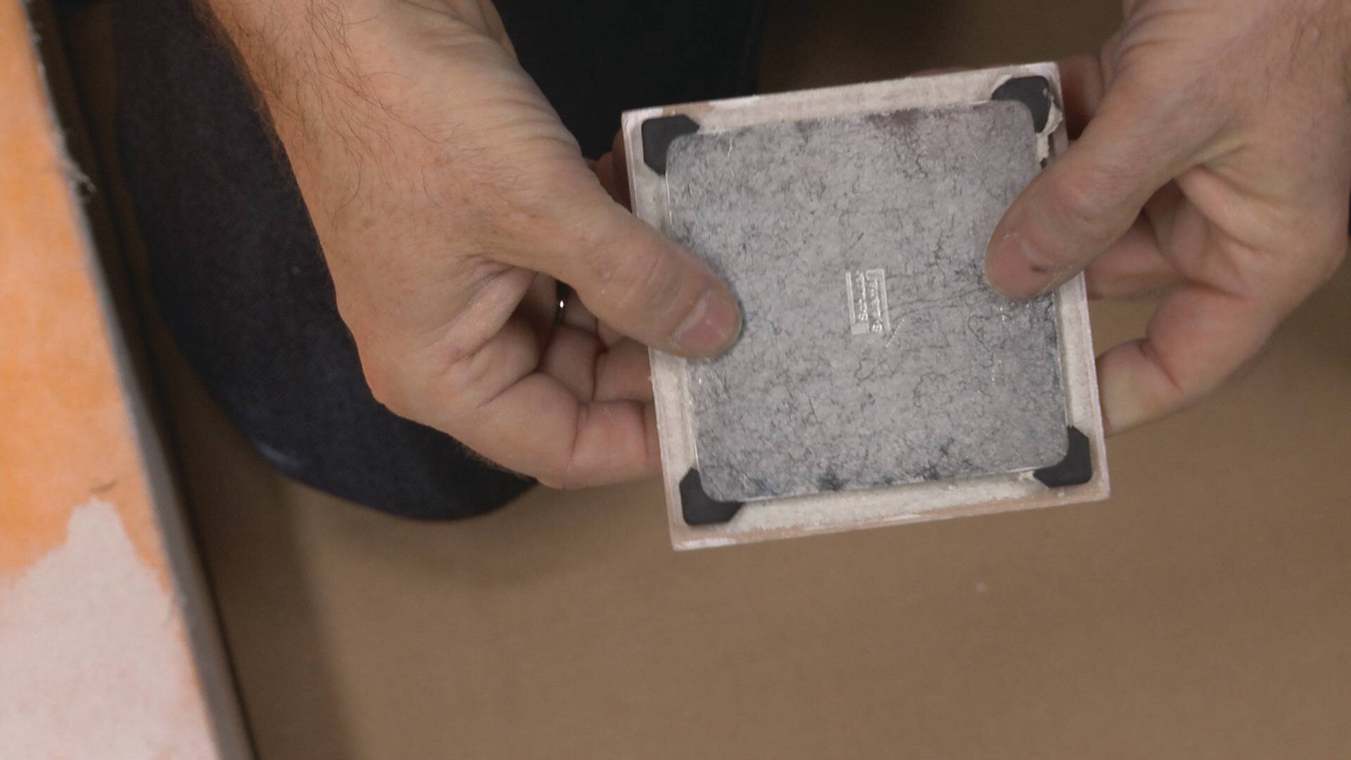
Instalar la baldosa sobre la rejilla portadora usando Schluter SET, ALL-SET, FAST-SET, o cualquier otro mortero adhesivo no modificado.
La baldosa puede sobrevolar la rejilla portadora, siempre y cuando se disponga de una apertura de drenaje un mínimo de 5 mm (3/16").
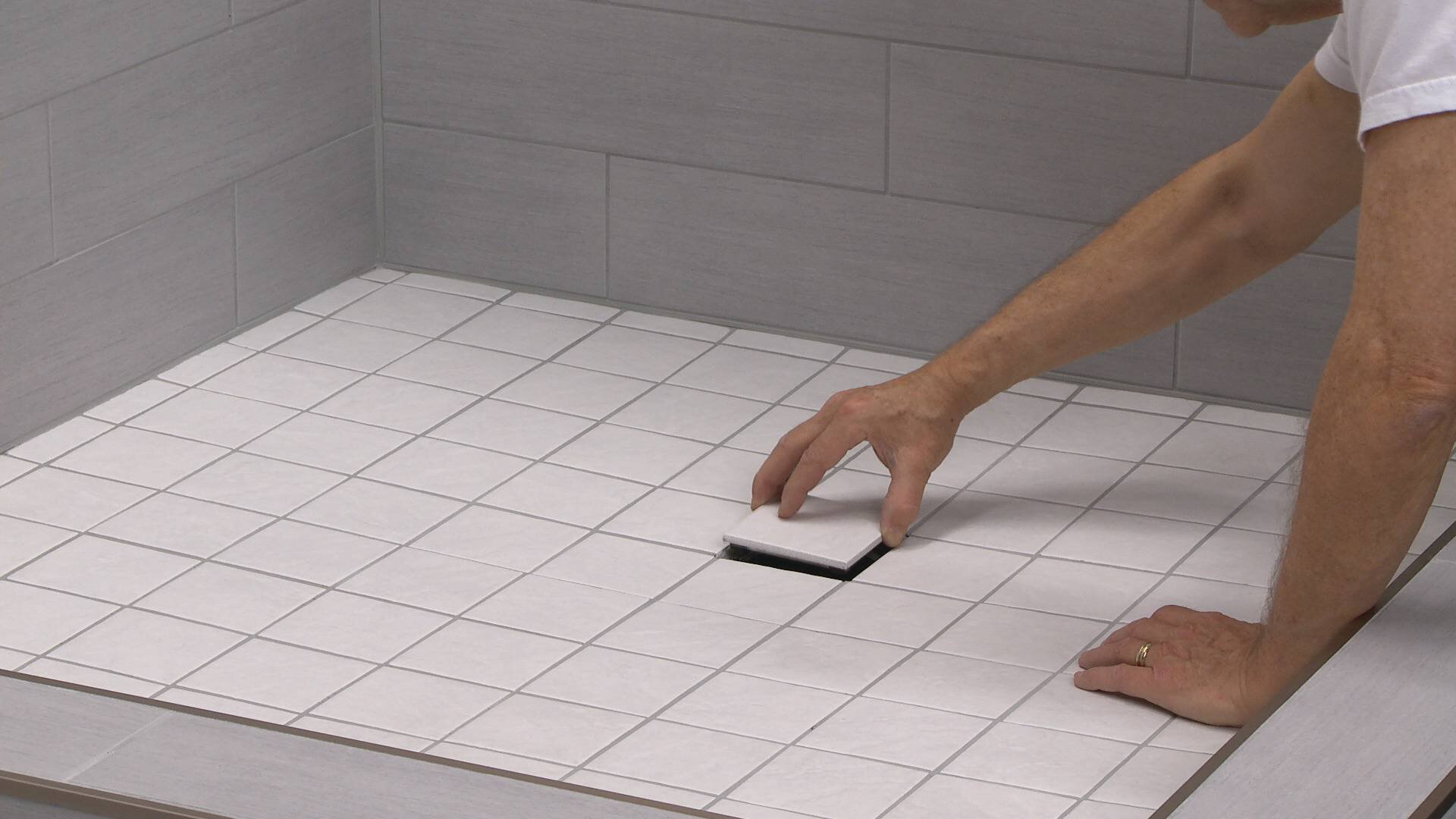
Una vez terminado el recubrimiento y rejuntado del conjunto, retirar el separador e insertar la rejilla portadora en el anillo de ajuste lateral.
Product page
